
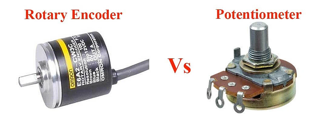
Rotary Encoder vs Potentiometer - Which Should You Use?
A Comprehensive Guide to Understanding the Differences, Working Principles, and Applications
When working on electronic projects, robotics, automation systems, or industrial applications, choosing the right input device for position sensing and control is crucial. Two of the most commonly used components for this purpose are Rotary Encoders and Potentiometers. While both devices serve similar purposes of converting mechanical motion into electrical signals, they operate on fundamentally different principles and offer distinct advantages depending on your specific application requirements.
In this comprehensive guide, we will explore everything you need to know about rotary encoders and potentiometers, including their working principles, types, key differences, advantages, disadvantages, and most importantly - when to use each one. By the end of this article, you will have a clear understanding of which component is best suited for your project.
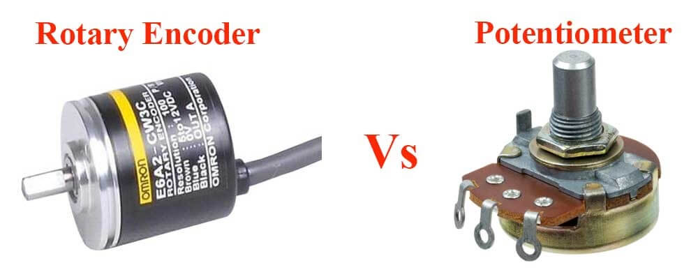
Figure 1: Visual comparison between Rotary Encoder and Potentiometer
Quick Comparison: Rotary Encoder vs Potentiometer
| Feature | Rotary Encoder | Potentiometer |
|---|---|---|
| Output Type | Digital pulses or codes | Analog voltage |
| Precision/Resolution | Very High (up to 10,000+ PPR) | Moderate (limited by track) |
| Durability/Lifespan | Very Long (non-contact types) | Moderate (wear over time) |
| Cost | Higher | Lower |
| Rotation | Continuous (no end stops) | Limited (has end stops) |
| Power Loss Behavior | Loses position (incremental) / Retains (absolute) | Always retains position |
| Environmental Tolerance | Excellent (many rugged options) | Moderate (sensitive to dust) |
| Integration Complexity | Requires microcontroller/software | Simple analog integration |
1. Understanding Potentiometers
1.1 What is a Potentiometer?
A potentiometer, often referred to as a "pot" or "variable resistor," is a three-terminal resistor with a sliding or rotating contact that forms an adjustable voltage divider. It is one of the most fundamental and widely used components in electronics, serving as a simple yet effective means of controlling voltage, current, and resistance in circuits.
The potentiometer operates on the principle of a voltage divider. When a voltage is applied across the two outer terminals, the position of the wiper (middle terminal) determines the output voltage, which can vary from zero to the full input voltage. This simple mechanism makes potentiometers incredibly versatile for countless applications.
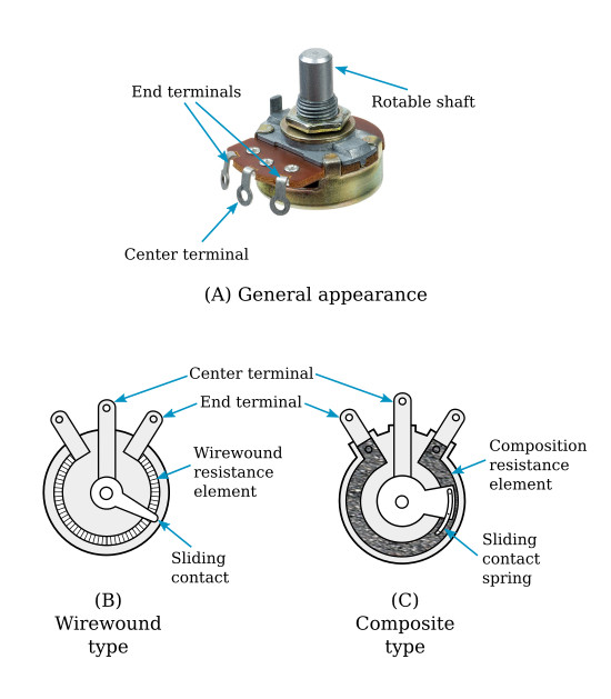
Figure 2: Potentiometer structure showing wirewound and composite types
1.2 Working Principle of Potentiometers
The working principle of a potentiometer is based on Ohm's Law and the concept of a voltage divider. Here's a detailed breakdown of how it works:
- Resistive Track: The core component is a resistive element, which can be made of carbon, cermet (ceramic-metal), conductive plastic, or wirewound material. This track has a uniform resistance per unit length.
- Wiper Contact: A movable wiper slides along the resistive track. The wiper is mechanically connected to the rotating shaft or sliding knob.
- Three Terminals: Two terminals are connected to the ends of the resistive track, while the third terminal is connected to the wiper.
- Voltage Division: When voltage is applied across the end terminals, the wiper picks off a fraction of this voltage proportional to its position along the track.
- Output: The voltage at the wiper terminal varies linearly (or logarithmically, depending on taper) with the position of the shaft.
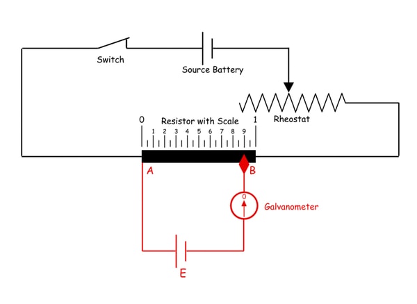
Figure 3: Potentiometer circuit diagram showing voltage divider principle
1.3 Types of Potentiometers
1.3.1 Rotary Potentiometers
Rotary potentiometers are the most common type, featuring a knob that rotates to adjust the resistance. They typically have a rotation range of 270 to 300 degrees with mechanical stops at both ends. These are widely used in:
- Audio equipment for volume control
- Light dimmers
- Fan speed controllers
- Analog synthesizers
- Electronic equipment calibration
1.3.2 Linear (Slide) Potentiometers
Linear potentiometers use a sliding mechanism instead of rotation. The wiper moves in a straight line along the resistive track. These are commonly found in:
- Audio mixing consoles
- Graphic equalizers
- Industrial control panels
- Joystick position sensing
- Robotic arm positioning
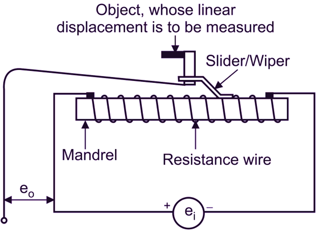
Figure 4: Linear potentiometer structure and working principle
1.3.3 Multi-Turn Potentiometers
Multi-turn potentiometers require several full rotations (typically 10, 20, or more turns) to travel the entire resistance range. This design provides finer adjustment and reduces wear. Applications include:
- Precision calibration equipment
- Laboratory instruments
- Aerospace systems
- Medical devices
- Test and measurement equipment
1.3.4 Trimmer Potentiometers
Trimmer potentiometers (or trim pots) are small, precision potentiometers designed for infrequent adjustment, typically during calibration or setup. They are commonly used for:
- Circuit calibration
- Offset adjustment
- Gain setting in amplifiers
- Voltage reference adjustment
1.3.5 Taper Types
Potentiometers also come in different taper types that define how resistance changes with shaft position:
- Linear Taper (B-type): Resistance changes evenly with shaft rotation. Ideal for calibration and sensor applications.
- Logarithmic Taper (A-type): Resistance changes logarithmically, providing finer control at lower settings. Perfect for audio volume controls because human hearing responds logarithmically.
- Anti-Logarithmic Taper (C-type): Opposite of logarithmic, used for specific audio tone controls.
1.4 Advantages of Potentiometers
- Low Cost: Potentiometers are inexpensive, making them ideal for cost-sensitive applications.
- Simple Integration: Direct analog output requires no additional processing circuits or software.
- Immediate Position Feedback: The output voltage directly represents position at all times, even after power loss.
- Wide Availability: Available in numerous sizes, resistance values, and configurations.
- Smooth Control: Provides continuous, smooth adjustment without discrete steps.
- No Software Required: Can be directly connected to analog inputs without programming.
1.5 Disadvantages of Potentiometers
- Wear and Tear: Physical contact between wiper and resistive track causes wear over time, leading to noise and eventual failure.
- Limited Lifespan: Typically rated for 10,000 to 100,000 cycles depending on quality.
- Environmental Sensitivity: Dust, moisture, and vibration can affect performance and accelerate wear.
- Temperature Drift: Resistance value can change with temperature variations.
- Limited Rotation: Most rotary types have mechanical stops (typically 270°-300°).
- Lower Precision: Resolution is limited by the physical size of the resistive track.
- Contact Noise: Wiper contact can generate electrical noise, especially as the device ages.
1.6 Common Applications of Potentiometers
| Application Area | Specific Uses | Recommended Type |
|---|---|---|
| Audio Equipment | Volume control, tone adjustment, balance | Rotary (Logarithmic) |
| Consumer Electronics | Brightness control, contrast adjustment | Rotary or Trimmer |
| Automotive | Throttle position sensors, dashboard controls | Rotary (Conductive Plastic) |
| Industrial | Motor speed control, calibration | Multi-turn (Cermet) |
| Gaming | Joystick position sensing | Linear or Rotary |
| Robotics | Joint position feedback | Linear or Rotary |
| Medical Equipment | Calibration, adjustment controls | Multi-turn (Cermet) |
2. Understanding Rotary Encoders
2.1 What is a Rotary Encoder?
A rotary encoder, also known as a shaft encoder, is an electromechanical device that converts the angular position or motion of a shaft or axle into analog or digital output signals. Unlike potentiometers, rotary encoders provide digital feedback and can rotate continuously without mechanical stops, making them ideal for applications requiring precise position tracking, speed measurement, and direction detection.
Rotary encoders are often referred to as the "eyes" of motion control systems because they provide critical feedback that enables closed-loop control. They are essential components in robotics, CNC machines, industrial automation, and any application where precise motion control is required.
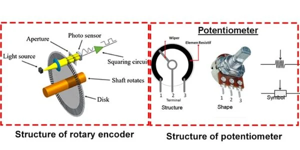
Figure 5: Structural comparison of rotary encoder and potentiometer
2.2 Working Principle of Rotary Encoders
Rotary encoders operate on different principles depending on their sensing technology. Here's a detailed explanation of how they work:
2.2.1 Optical Rotary Encoders
Optical encoders are the most common type and offer the highest precision. Their working principle involves:
- Code Disc: A glass or plastic disc with precisely etched transparent and opaque sections is attached to the rotating shaft.
- Light Source: An LED or infrared light source is positioned on one side of the disc.
- Photodetectors: Optical sensors (photodiodes or phototransistors) are placed on the opposite side.
- Signal Generation: As the disc rotates, light passes through transparent sections and is blocked by opaque sections, creating pulses of light.
- Electrical Output: Photodetectors convert these light pulses into electrical signals.
- Quadrature Output: Two channels (A and B) produce square waves 90 degrees out of phase, enabling direction detection.
2.2.2 Magnetic Rotary Encoders
Magnetic encoders use Hall effect sensors or magnetoresistive sensors to detect changes in magnetic fields:
- Magnet: A permanent magnet (typically neodymium) is attached to the rotating shaft.
- Hall Sensors: Hall effect sensors detect changes in the magnetic field as the magnet rotates.
- Signal Processing: The sensor output is processed to determine position and direction.
- Advantages: More resistant to dust, dirt, and moisture compared to optical encoders.
2.2.3 Mechanical (Contact) Rotary Encoders
Mechanical encoders use physical contacts and are the simplest and least expensive type:
- Contact Pattern: A patterned conductive track rotates with the shaft.
- Brushes/Contacts: Spring-loaded contacts slide against the track.
- Signal Generation: Contact between brushes and track creates electrical pulses.
- Limitations: Subject to wear and contact bounce, resulting in shorter lifespan.
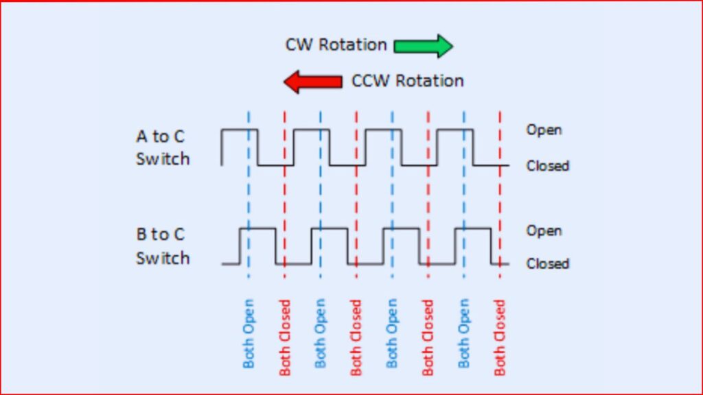
Figure 6: Quadrature output signals showing clockwise and counter-clockwise rotation detection
2.3 Types of Rotary Encoders
2.3.1 Incremental Rotary Encoders
Incremental encoders generate a series of pulses as the shaft rotates. They provide relative position information and require a reference point to determine absolute position.
Key Characteristics:
- Output two channels (A and B) with quadrature phase relationship
- Resolution measured in Pulses Per Revolution (PPR) - common values: 100, 360, 500, 1000, 1024, 2048, 4096 PPR
- Can include a third channel (Z or Index) that pulses once per revolution for homing
- Lose position information when power is removed
- Require counting circuitry or microcontroller to track position
- Can measure speed and direction
Common Applications:
- Motor speed and position feedback
- Conveyor belt monitoring
- CNC machine tool positioning
- Robotics joint control
- Printing machinery
- Packaging equipment
2.3.2 Absolute Rotary Encoders
Absolute encoders provide a unique digital code for each shaft position, allowing the system to know the exact position immediately upon power-up without requiring a reference move.
Key Characteristics:
- Output parallel or serial digital code representing absolute position
- Retain position information even after power loss
- Resolution measured in bits (e.g., 10-bit = 1024 positions, 12-bit = 4096 positions)
- Single-turn: Measures position within one revolution (0-360°)
- Multi-turn: Measures position across multiple revolutions (can track thousands of turns)
- More expensive than incremental encoders
- No need for homing sequence
Common Applications:
- Surgical robots and medical equipment
- Aerospace and defense systems
- Wind turbine blade positioning
- Satellite antenna positioning
- Industrial robots requiring absolute positioning
- Elevator control systems
2.3.3 Encoder Output Types
| Output Type | Description | Best For |
|---|---|---|
| Open Collector | Transistor output, requires pull-up resistor | Simple applications, short cable runs |
| Push-Pull (Totem Pole) | Active high and low output | General purpose, better noise immunity |
| Line Driver (Differential) | RS422 differential signals (A, A-, B, B-) | Long cable runs, noisy environments |
| SSI (Synchronous Serial) | Serial interface for absolute encoders | Absolute encoders, industrial applications |
2.4 Advantages of Rotary Encoders
- High Precision: Can provide resolution up to 10,000+ pulses per revolution or higher.
- Continuous Rotation: No mechanical stops - can rotate indefinitely in either direction.
- Digital Output: Clean digital signals immune to analog noise and drift.
- Direction Detection: Quadrature output allows detecting rotation direction.
- Speed Measurement: Pulse frequency directly indicates rotation speed.
- Long Lifespan: Non-contact optical and magnetic types have virtually unlimited life.
- Non-Contact Options: Optical and magnetic encoders have no wearing parts.
- Harsh Environment Capability: Many models are sealed against dust, moisture, and vibration.
- Absolute Position: Absolute encoders retain position even after power loss.
2.5 Disadvantages of Rotary Encoders
- Higher Cost: Generally more expensive than potentiometers, especially high-resolution models.
- Complex Integration: Requires microcontroller or dedicated counter circuitry.
- Software Required: Incremental encoders need software to count pulses and track position.
- Power Loss Issue: Incremental encoders lose position when power is removed.
- Environmental Sensitivity (Optical): Optical encoders can be affected by dust and dirt.
- Electrical Noise: Mechanical encoders can suffer from contact bounce.
- Higher Power Consumption: Especially optical encoders with LED light sources.
2.6 Common Applications of Rotary Encoders
| Industry/Application | Specific Uses | Encoder Type |
|---|---|---|
| Industrial Automation | Motor feedback, conveyor positioning, assembly machines | Incremental, Optical |
| CNC Machines | Spindle speed, axis positioning, tool changers | Incremental/Absolute, High Resolution |
| Robotics | Joint position, arm movement, mobile robot navigation | Absolute, Multi-turn |
| Medical Equipment | Surgical robots, MRI positioning, infusion pumps | Absolute, High Precision |
| Aerospace | Flight control surfaces, navigation systems | Absolute, Rugged |
| Elevators | Car positioning, speed control, door operation | Absolute, Multi-turn |
| Automotive | Steering angle, wheel speed, throttle position | Magnetic, Hall Effect |
| Renewable Energy | Wind turbine blade angle, solar tracker position | Absolute, Multi-turn |
| Consumer Electronics | Volume controls, menu navigation, gaming controllers | Mechanical, Low-cost |
3. Detailed Technical Comparison
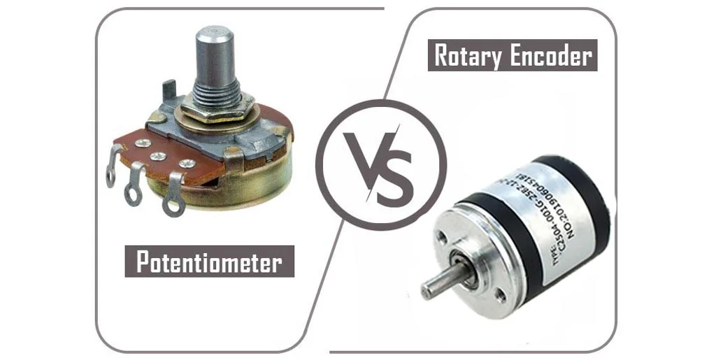
Figure 7: Side-by-side comparison of potentiometer and rotary encoder
3.1 Output Signal Comparison
Potentiometer Output
- Analog Voltage: Output is a continuous voltage between 0V and Vcc
- Direct Reading: Can be connected directly to ADC (Analog-to-Digital Converter)
- Resolution Limited: By ADC resolution and noise
- No Processing Required: Simple voltage divider output
- Example: With 5V supply and 10-bit ADC, resolution is 5V/1024 ≈ 4.9mV per step
Rotary Encoder Output
- Digital Pulses: Square wave output with discrete transitions
- Quadrature Signals: Two channels (A and B) 90° out of phase
- High Resolution: Can detect 4x the PPR by counting both edges of both channels
- Requires Processing: Needs microcontroller to count pulses and determine direction
- Example: 1000 PPR encoder can provide 4000 counts per revolution with quadrature decoding
3.2 Resolution and Precision
| Parameter | Potentiometer | Rotary Encoder |
|---|---|---|
| Typical Resolution | 8-12 bits (256-4096 steps) | Up to 16+ bits (65,536+ steps) |
| Angular Resolution | ~0.35° (10-bit, 270° range) | ~0.09° (1000 PPR with quadrature) |
| Repeatability | Moderate (affected by wear) | Excellent (digital precision) |
| Linearity | ±1-5% (varies by type) | ±0.1% or better |
3.3 Durability and Lifespan
Potentiometer Lifespan
- Carbon: 10,000 - 50,000 cycles
- Cermet: 50,000 - 100,000 cycles
- Conductive Plastic: 100,000 - 1,000,000 cycles
- Wirewound: 50,000 - 200,000 cycles
- Wear Factors: Contact pressure, environmental contamination, rotation speed
Rotary Encoder Lifespan
- Mechanical: 100,000 - 1,000,000 cycles (contact wear)
- Optical: Virtually unlimited (LED life: 50,000-100,000 hours)
- Magnetic: Virtually unlimited (no wearing parts)
- Failure Modes: LED degradation (optical), bearing wear, contamination
3.4 Environmental Considerations
| Environmental Factor | Potentiometer | Rotary Encoder |
|---|---|---|
| Dust/Dirt | Sensitive - causes wear and noise | Magnetic: Good, Optical: Poor |
| Moisture | Can cause corrosion and failure | Sealed models available |
| Vibration | Can affect contact quality | Generally well-tolerated |
| Temperature | Resistance drift with temperature | More stable, wider range options |
| Electrical Noise | Susceptible to noise | Digital signals more immune |
3.5 Cost Comparison
| Component Type | Typical Price Range | Notes |
|---|---|---|
| Basic Carbon Potentiometer | ₹10 - ₹50 | Consumer grade, short lifespan |
| Cermet Potentiometer | ₹50 - ₹200 | Better stability and lifespan |
| Precision Multi-turn Pot | ₹200 - ₹1000+ | High precision applications |
| Mechanical Encoder (Basic) | ₹50 - ₹200 | Low resolution, contact type |
| Optical Incremental Encoder | ₹500 - ₹5000+ | Depends on resolution and features |
| Absolute Encoder | ₹2000 - ₹20,000+ | High precision, retains position |
4. When to Use a Potentiometer
Choose a potentiometer when your application meets the following criteria:
4.1 Ideal Scenarios for Potentiometers
✓ Cost-Sensitive Applications
When budget is a primary concern and basic position sensing is sufficient. Potentiometers offer the most economical solution for simple control applications.
✓ Simple Analog Control
When you need direct voltage control without additional processing. Perfect for volume controls, dimmers, and basic speed adjustment.
✓ Position Must Be Retained After Power Loss
When the system needs to know its position immediately upon power-up without homing. Potentiometers always indicate absolute position.
✓ Limited Rotation Range
When the control only needs to move within a limited range (e.g., 270° for volume control).
✓ No Microcontroller Available
When you need a simple solution without programming. Potentiometers work with simple analog circuits.
✓ Smooth, Continuous Adjustment
When you need stepless, smooth control without discrete steps or detents.
4.2 Specific Use Cases for Potentiometers
- Audio Equipment: Volume controls, tone adjustments, balance controls
- Lighting Control: Dimmer switches, brightness adjustment
- Consumer Electronics: TV contrast/brightness, appliance controls
- Test Equipment: Calibration adjustments, reference setting
- Automotive: Dashboard controls, climate control, simple throttle sensors
- Educational Projects: Learning basic electronics and analog circuits
- Hobby Projects: Arduino/Raspberry Pi analog input experiments
- Industrial: Manual setpoint adjustment, calibration trimmers
5. When to Use a Rotary Encoder
Choose a rotary encoder when your application requires:
5.1 Ideal Scenarios for Rotary Encoders
✓ High Precision Positioning
When you need precise position feedback with resolution of 0.1° or better. Essential for CNC machines, robotics, and precision automation.
✓ Continuous Rotation Required
When the control needs to rotate indefinitely without mechanical stops. Perfect for menu navigation and infinite adjustment.
✓ Direction Detection Needed
When your application needs to know which direction the shaft is rotating.
✓ Speed Measurement
When you need to measure or control rotational speed. Encoders provide direct speed feedback through pulse frequency.
✓ Long-Term Reliability
When the device will be used frequently over a long period. Non-contact encoders have virtually unlimited life.
✓ Digital System Integration
When working with microcontrollers, PLCs, or digital control systems that can process encoder signals.
✓ Harsh Environment Operation
When operating in dusty, dirty, or vibration-prone environments. Sealed and magnetic encoders excel here.
5.2 Specific Use Cases for Rotary Encoders
- CNC Machines: Precise axis positioning, spindle speed control, tool changers
- Industrial Robotics: Joint position feedback, arm movement control
- Servo Motor Control: Closed-loop position and speed control
- 3D Printers: Print head positioning, bed leveling
- Automated Manufacturing: Assembly line positioning, quality control
- Medical Equipment: Surgical robot positioning, diagnostic equipment
- Aerospace: Flight control surfaces, navigation systems
- Renewable Energy: Wind turbine blade angle, solar tracker positioning
- Elevator Systems: Car positioning, door control, speed regulation
- User Interfaces: Menu navigation, digital controls with detents
- Test and Measurement: Precise angle measurement, calibration equipment
6. Decision Guide: Choosing Between Potentiometer and Rotary Encoder
Use this decision tree to help determine which component is right for your application:
Decision Questions:
Q1: Do you need precision better than 1 degree?
YES → Consider Rotary Encoder
NO → Potentiometer may be sufficient
Q2: Does your application require continuous rotation?
YES → Rotary Encoder is required
NO → Either option may work
Q3: Is cost a major constraint?
YES → Potentiometer is more economical
NO → Consider other factors
Q4: Do you have a microcontroller in your system?
YES → Rotary Encoder can be easily integrated
NO → Potentiometer is simpler to implement
Q5: Will the device be used frequently (>1000 cycles/day)?
YES → Rotary Encoder (non-contact type recommended)
NO → Potentiometer should suffice
Q6: Is the operating environment harsh (dusty, wet, high vibration)?
YES → Sealed Rotary Encoder (magnetic or optical)
NO → Either option, consider other factors
Q7: Do you need to detect rotation direction?
YES → Rotary Encoder with quadrature output
NO → Either option may work
6.1 Application-Specific Recommendations
| Application | Recommended Choice | Reasoning |
|---|---|---|
| Audio Volume Control | Potentiometer | Simple, cost-effective, smooth control |
| CNC Machine Axis | Rotary Encoder | High precision, direction detection needed |
| Light Dimmer Switch | Potentiometer | Simple analog control, cost-effective |
| 3D Printer | Rotary Encoder | High precision positioning required |
| Dashboard Controls | Potentiometer | Simple, reliable, immediate feedback |
| Servo Motor Feedback | Rotary Encoder | Precise position control, speed feedback |
| Menu Navigation Knob | Rotary Encoder | Continuous rotation, detents for feedback |
| Calibration Trimmer | Potentiometer | Fine adjustment, set-and-forget |
| Robotic Arm Joint | Rotary Encoder | Absolute position, high precision |
| Fan Speed Control | Potentiometer | Simple speed adjustment, low cost |
7. Wiring and Implementation Guide
7.1 Potentiometer Wiring
Wiring a potentiometer is straightforward:
- Pin 1 (Outer): Connect to ground (0V)
- Pin 2 (Wiper/Middle): Connect to analog input (output voltage)
- Pin 3 (Outer): Connect to Vcc (typically 3.3V or 5V)
Arduino Example: Connect the wiper to analog pin A0. Use analogRead(A0) to read values from 0 to 1023 (10-bit ADC).
7.2 Rotary Encoder Wiring
A typical incremental rotary encoder has the following connections:
- Vcc: Power supply (3.3V or 5V)
- GND: Ground connection
- Channel A: Connect to digital input with interrupt capability
- Channel B: Connect to digital input (for direction detection)
- Channel Z (Index): Optional - one pulse per revolution for homing
Arduino Example: Connect Channel A to pin 2 (interrupt) and Channel B to pin 3. Use interrupt service routines to count pulses and determine direction.
7.3 Code Examples
Arduino Code for Potentiometer
// Potentiometer Reading Example
const int potPin = A0;  // Potentiometer connected to analog pin A0

void setup() {
  Serial.begin(9600);
}

void loop() {
  int potValue = analogRead(potPin);  // Read value (0-1023)
  float voltage = potValue * (5.0 / 1023.0);  // Convert to voltage
  int angle = map(potValue, 0, 1023, 0, 270);  // Map to angle (assuming 270° pot)

  Serial.print("Value: ");
  Serial.print(potValue);
  Serial.print(" | Voltage: ");
  Serial.print(voltage);
  Serial.print("V | Angle: ");
  Serial.print(angle);
  Serial.println("°");

  delay(100);
}
Arduino Code for Rotary Encoder
// Rotary Encoder Example with Interrupt
#define ENCODER_PIN_A 2  // Must be interrupt pin
#define ENCODER_PIN_B 3

volatile long encoderPosition = 0;
int lastEncoded = 0;

void setup() {
  Serial.begin(9600);

  pinMode(ENCODER_PIN_A, INPUT_PULLUP);
  pinMode(ENCODER_PIN_B, INPUT_PULLUP);

  // Attach interrupt for encoder
  attachInterrupt(digitalPinToInterrupt(ENCODER_PIN_A),
                  updateEncoder, CHANGE);
}

void loop() {
  Serial.print("Position: ");
  Serial.println(encoderPosition);
  delay(100);
}

void updateEncoder() {
  int MSB = digitalRead(ENCODER_PIN_A);
  int LSB = digitalRead(ENCODER_PIN_B);

  int encoded = (MSB << 1) | LSB;
  int sum = (lastEncoded << 2) | encoded;

  // Determine direction from state transition
  if(sum == 0b1101 || sum == 0b0100 ||
     sum == 0b0010 || sum == 0b1011) {
    encoderPosition++;
  }
  if(sum == 0b1110 || sum == 0b0111 ||
     sum == 0b0001 || sum == 0b1000) {
    encoderPosition--;
  }

  lastEncoded = encoded;
}
8. Popular Products Available at FlyRobo
At FlyRobo.in, we offer a wide range of potentiometers and rotary encoders to suit various applications. Here are some of our popular products:
8.1 Potentiometers
| Product | Best For |
|---|---|
| 10K Ohm Rotary Potentiometer | General purpose, Arduino projects |
| B10K Audio Potentiometer | Audio volume control |
| Slide Potentiometer 10K | Audio mixers, faders |
| Joystick Module | Gaming, robot control |
8.2 Rotary Encoders
| Product | Best For |
|---|---|
| KY-040 Rotary Encoder Module | Arduino projects, menu navigation |
| 15mm EC11 Rotary Encoder | Motor feedback, positioning |
| EC11 Rotary Encoder | Consumer electronics, UI |
| Digital Rotary Encoder Module | Consumer electronics, UI |
9. Troubleshooting Common Issues
9.1 Potentiometer Issues
| Problem | Cause | Solution |
|---|---|---|
| Noisy or erratic output | Worn wiper, dust on track | Clean with contact cleaner or replace |
| Dead spots | Worn resistive track | Replace potentiometer |
| Output doesn't reach 0 or max | Incorrect wiring or faulty pot | Check connections, verify potentiometer |
| Drifting readings | Temperature changes, aging | Use cermet type, add software filtering |
9.2 Rotary Encoder Issues
| Problem | Cause | Solution |
|---|---|---|
| Missed counts | Slow polling, no interrupts | Use interrupt-based reading |
| Wrong direction detection | Swapped A/B channels | Swap A and B connections |
| Bounce/noise | Mechanical contact bounce | Add debouncing in software or hardware |
| Position lost on reset | Incremental encoder | Implement homing routine or use absolute encoder |
10. Conclusion
Both potentiometers and rotary encoders are valuable components in the world of electronics and automation, each with their own strengths and ideal use cases. Understanding their differences is key to selecting the right component for your project.
Key Takeaways
- Choose a Potentiometer when: You need a simple, cost-effective solution for basic position control, analog voltage output, and applications where absolute position must be known immediately after power-up without additional processing.
- Choose a Rotary Encoder when: You need high precision, continuous rotation, direction detection, speed measurement, or operation in demanding environments. Encoders are essential for modern digital control systems.
The decision ultimately depends on your specific application requirements including precision needs, budget constraints, environmental conditions, and system complexity. For many hobby and educational projects, potentiometers offer an excellent starting point due to their simplicity and low cost. As your projects become more advanced, incorporating rotary encoders will unlock new capabilities for precision control and feedback.
Ready to Get Started?
Visit www.flyrobo.in to explore our comprehensive range of potentiometers, rotary encoders, and other electronic components. We offer high-quality products at competitive prices with fast shipping across India. Whether you're a hobbyist, student, or professional, we have the right components for your next project!
Frequently Asked Questions (FAQ)
Q1: Can I replace a potentiometer with a rotary encoder in my existing circuit?
A: Direct replacement is not possible because potentiometers output analog voltage while encoders output digital pulses. To use an encoder, you'll need a microcontroller to read the pulses and convert them to a usable control signal. The circuit and software will need to be modified accordingly.
Q2: Why do rotary encoders cost more than potentiometers?
A: Rotary encoders contain more complex components including precision optics or magnetic sensors, signal processing electronics, and higher-precision mechanical parts. The manufacturing process is also more complex. However, the added cost brings significant benefits in precision, durability, and functionality.
Q3: Do rotary encoders need batteries to remember position?
A: Incremental encoders lose position when power is removed and don't need batteries. Absolute encoders retain position without power through mechanical or electronic means (like a battery-backed memory in some models). Multi-turn absolute encoders may use batteries or gearing to track multiple rotations.
Q4: Can I use a potentiometer for motor speed control?
A: Yes, for simple DC motor speed control, a potentiometer can be used with a motor driver to vary the voltage. However, for precise speed control with feedback, a rotary encoder paired with a closed-loop controller is recommended for better accuracy and stability.
Q5: What is the maximum rotation speed for encoders?
A: Maximum speed varies by encoder type. Mechanical encoders typically handle up to a few hundred RPM, while optical encoders can operate at 10,000+ RPM. Always check the datasheet for the specific maximum speed rating.
Q6: Are there digital potentiometers available?
A: Yes, digital potentiometers (digipots) are available and can be controlled via digital interfaces like I2C or SPI. They offer the convenience of software control while maintaining analog output. These are useful for automated calibration and remote adjustment applications.
Q7: How do I calculate the resolution I need?
A: For potentiometers, resolution depends on ADC bits. For encoders, resolution is typically specified in PPR (Pulses Per Revolution). With quadrature decoding, you get 4x the PPR in counts per revolution. For example, a 1000 PPR encoder provides 4000 counts per revolution, giving 0.09° resolution.
About FlyRobo
FlyRobo is India's leading online store for electronic components, robotics parts, DIY kits, and automation solutions. We cater to hobbyists, students, engineers, and professionals with a wide range of quality products at competitive prices. Our mission is to make electronics and robotics accessible to everyone.

Leave a Comment