
As the name suggests, the self-balancing robot is an automated vehicle that balances itself without any outside help or support. This project is a rather complex one as it involves using PID Control and involuted programming.
Self-balancing robots are unique among all others, just because of their ability to balance on a given fixed position. Even if the robot is displaced from its position, it is programmed so that it again recovers its position.
In this tutorial-based article, we will teach you how to make a working model of a Self-balancing robot using Arduino Nano.
The working concept of a Self-balancing Robot
The concept of a Self-balancing robot is related to the Proportional-Integral-Derivative control (PID). A gyroscope is used to measure the angle and choose the setpoint for the PID Control.
The gyroscope used in this case is MPU6050. As the angle of the robot changes, the Arduino sends the signal to the L298N motor driver to direct the motors in such a way that it counters the fall of the robot. This in turn helps the robot to balance itself upright.
This robot can be used in various industries like automated production processes, Military applications, etc.
Hardware Required
Software Required
Arduino Nano
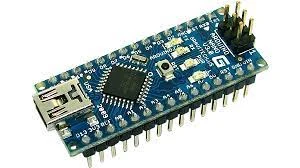
The Arduino Nano is a small, complete, and breadboard-friendly board based on the processor ATmega328. It almost has the same functionality as the Arduino Duemilanove, but with a different configuration. It does not have a direct power jack and works with a Mini-B USB cable instead of a standard one.
MPU6050
.webp)
MPU-6050 is a 3-Axis accelerometer and 3-Axis gyroscope module on the same silicon together with an onboard Digital Motion Processor (DMP) capable of processing complex 9-axis Motion fusion algorithms.
L298N Motor driver
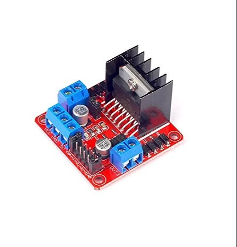
L298N motor driver is perfect for driving DC motors and Stepper motors. It can control 4 DC motors or 2 DC motors with direction and speed control. This motor driver is perfect for robotics projects and perfect for controlling motors from microcontrollers. Perfect for driving DC stepper motors for micro line-follower robots, robot arms, etc.
Bo geared motors
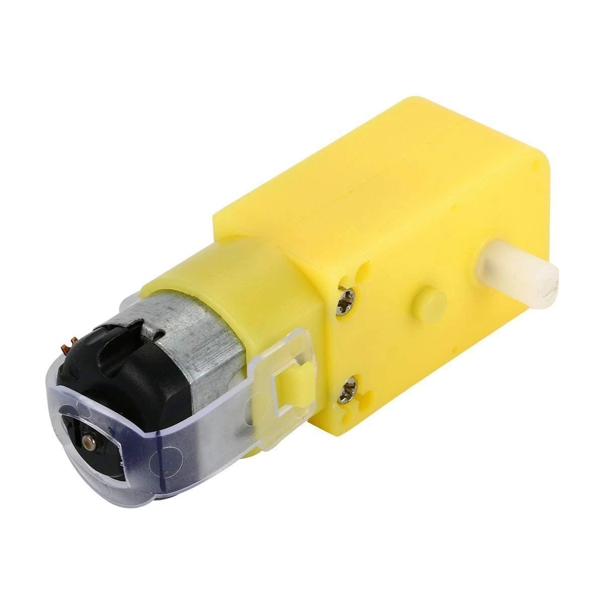
This Duel shaft motor gives good rpm and torque at low operating voltages, which is one of the biggest advantages of these motors. It is an alternative to our metal gear DC motors. It has an operating voltage of 3-6V which is perfect for building medium to small-sized robots. Mounting holes on the body of the motor and its lightweight qualities make it suitable for in-circuit placement. The motor is ideal for DIY enthusiasts. This motor is very economical, small, easy to install, and ideally suited for mobile robots.
Li-ion battery
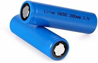
18650 is a single cell, compact and powerful cell with a 2200 mAh capacity. It is very convenient to fulfill the 3.7 Volt requirement with this cell. The battery terminals can use in any compatible battery adapter/holder or they can be permanently soldered to your application's power source wires.
Making the Frame
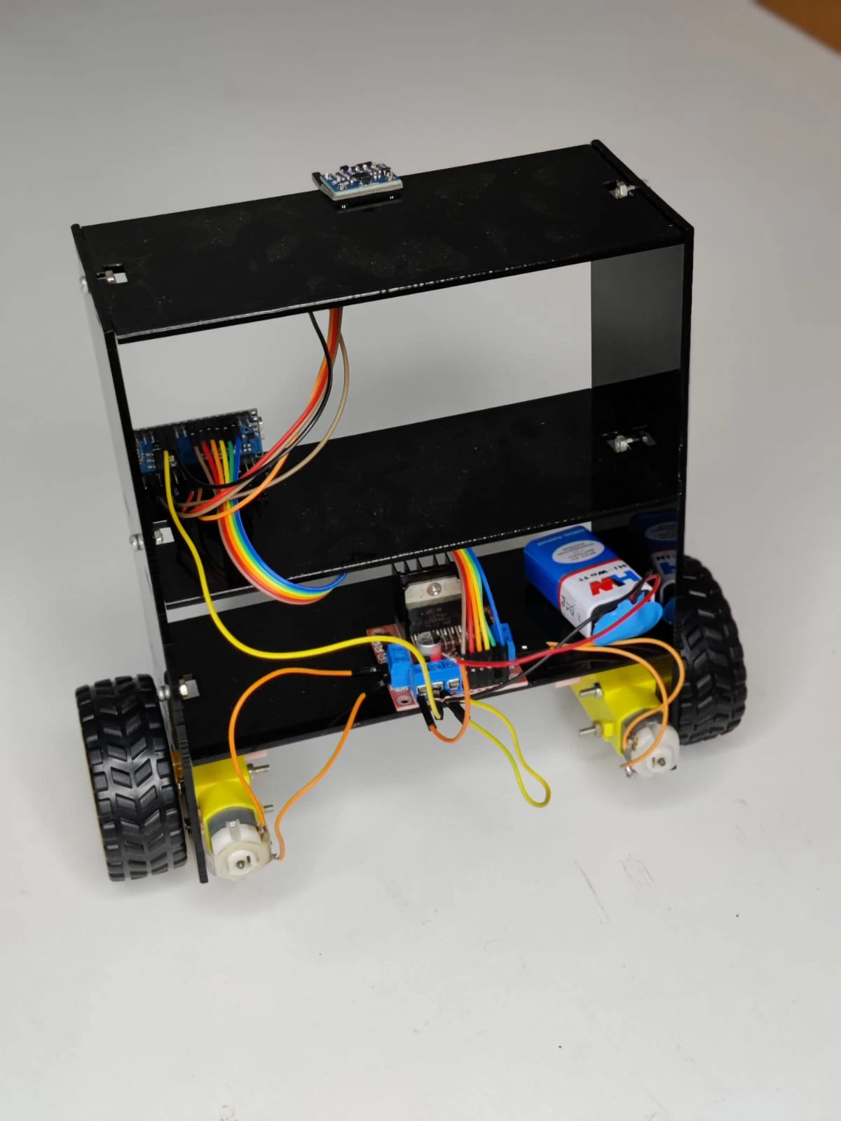
For this project, we have used a custom-made frame that is easily available from the internet. We designed our frame and then got it laser cut on an acrylic sheet. While making a frame try to keep the heavy stuff towards the bottom like the battery and motor driver this helps to bring the center of gravity towards the base and helps the robot to keep balance. also, try to keep the overall height of the frame low but not less than the base length
Circuit Diagram
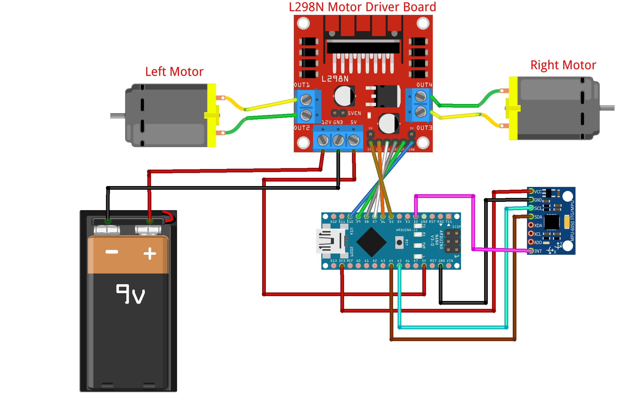
Wiring for this robot is simple, the MPU 6050 measures the tilt, and Arduino sets the motor speed to overcome tilt using the L298N motor driver.
Here we are using MPU-6050 because it is an economical and reliable sensor. Having accuracy and its ability to simultaneously measure all three axis rotation and motion makes it perfect for use in self-balancing robots.L298N is also a low-cost dual H-bridge motor driver perfect for use here.
On the assembly with the frame, the MPU-6050 is placed on top facing its Z-axis towards the earth. However, you can place this sensor anywhere in the frame. Also, the orientation can be changed according to frame and design, for this you have to make changes in code.
As we are using L298N as a motor driver and also as a power supply for Arduino so place the power jumper, So that we can use a +5v pin as a power supply.
The rest of the wiring is done according to the diagram given.
Arduino Code
Install the required libraries. Upload the code to the Arduino board.
Balancing test and Tuning
Self-balancing robots of this type are inverted pendulums, it is similar to balancing a stick on your finger. Here the rotation of wheels provides the counterbalancing force against fall. To balance this robot you have to configure the PID values till the robot attains a stable position and recovering ability.
To make this task simple code uses the ready-made library for Arduino PID. For adjusting PID according to your design you have to manually enter P, I, D values and check for stability by uploading code to Arduino in the following section of the code in the above-shown image.
The method to do this is first set Ki, Kd both 0, then put values for Kp then upload the code. after several attempts, the robot remains balanced for some time but rolls over-performing oscillations, this is the time when you have to set the Kd value without disturbing the Kp value. set Kd so that the minimum oscillations take place, this adjusts the Ki manually just like the other two.
Moreover, you can also set the setpoint values and offset for angles in the above-shown image. But it is not required in many cases and to set only when your gyroscope is having offsets.
After this trial and and error phase you will find suitable values for your robot. This process is bit tricky and sometimes it takes hours to find perfect value if you are beginner and new to control systems.
Uploading the Final code and powering
After doing trial and error with the PID values and uploading and testing the code multiple times, it is time to upload the final code on Arduino and check if the robot balances itself.
Now you can power the Arduino Nano from L298N. after resetting, hold in up straight position for a while. During this time MPU-6050 will calibrate. once done you are ready with your robot.
Now your self-balancing robot is ready to use!


Leave a Comment