

How Does a Potentiometer Work? A Complete Technical Guide
Understanding the Working Principle, Types, and Applications of Variable Resistors in Electronics
Published: January 2026 | Reading Time: 15 minutes
A potentiometer, commonly known as a "pot," is one of the most fundamental and widely used electronic components in the world of electronics and electrical engineering. Whether you're adjusting the volume on your stereo, controlling the speed of a motor, or calibrating sensitive measurement equipment, you're likely using a potentiometer. But how exactly does a potentiometer work?
In this comprehensive guide, we'll dive deep into the working principle of potentiometers, explore their construction, understand different types, and learn about their countless applications in modern electronics. By the end of this article, you'll have a thorough understanding of this essential component and how to use it effectively in your projects.
Table of Contents
- 1. What is a Potentiometer?
- 2. How Does a Potentiometer Work? (Working Principle)
- 3. Construction and Components
- 4. Potentiometer Circuit Symbol and Pinout
- 5. Types of Potentiometers
- 6. Understanding Potentiometer Taper (Linear vs Logarithmic)
- 7. Wiring Configurations: Voltage Divider vs Rheostat
- 8. Common Applications of Potentiometers
- 9. Digital Potentiometers (Digipots)
- 10. How to Choose the Right Potentiometer
1. What is a Potentiometer?
A potentiometer is a three-terminal variable resistor that allows you to manually adjust the resistance in an electrical circuit. Unlike fixed resistors that have a constant resistance value, potentiometers enable you to vary the resistance by moving a mechanical wiper along a resistive element. This simple yet powerful functionality makes potentiometers indispensable in countless electronic applications.
The name "potentiometer" comes from the combination of "Potential Difference" and "Metering." Historically, these devices were used to measure and divide electrical potential (voltage) in circuits. Today, they serve multiple purposes including voltage division, current control, and position sensing.
Key Characteristics of Potentiometers:
- Three-terminal device: Two fixed terminals and one movable wiper terminal
- Passive component: Requires no external power to function
- Adjustable resistance: Resistance can be varied smoothly or in steps
- Voltage divider: Can divide input voltage into smaller, adjustable outputs
- Manual control: Operated by rotating a knob or sliding a lever
Potentiometers are also known by several other names including variable resistors, pots, trim pots (when used for calibration), and rheostats (when used as two-terminal variable resistors). Understanding these terms will help you navigate datasheets and circuit diagrams more effectively.
2. How Does a Potentiometer Work? (Working Principle)
The fundamental working principle of a potentiometer is based on voltage division. When a voltage is applied across the two end terminals of the potentiometer, the movable wiper picks up a fraction of this voltage depending on its position along the resistive track. This allows the potentiometer to act as an adjustable voltage divider.
The Voltage Divider Principle
When you apply a voltage (Vin) across the two outer terminals of a potentiometer, the resistive element creates a continuous path for current flow. The wiper, which makes contact with this resistive element at a variable point, divides the total resistance into two parts: R1 (between terminal 1 and the wiper) and R2 (between the wiper and terminal 3).

Figure 1: Internal structure of a potentiometer showing the wiper moving along the resistive strip
The output voltage (Vout) at the wiper terminal is determined by the position of the wiper along the resistive track. Using the voltage divider formula:
Example: If you have a 10kΩ potentiometer with 10V applied across it, and the wiper is positioned at the midpoint:
- R1 = 5kΩ (first half)
- R2 = 5kΩ (second half)
- Vout = 10V × (5kΩ / 10kΩ) = 5V
If you move the wiper to 30% of the travel from the ground terminal, the output voltage becomes 3V. At 70% position, you get 7V. This linear relationship (for linear taper pots) makes potentiometers incredibly useful for creating adjustable voltage references and control signals.
Mechanical Operation
The mechanical operation involves a wiper (sliding contact) that moves along a resistive element. This movement can be:
- Rotary motion: The most common type where turning a shaft rotates the wiper around a circular resistive track
- Linear motion: The wiper moves in a straight line along a linear resistive strip, common in slide potentiometers and faders
As the wiper moves, it changes the ratio of resistances on either side of the contact point, thereby changing the output voltage. The resistive element is typically made from carbon composition, conductive plastic, cermet (ceramic-metal), or wire-wound materials, each offering different characteristics.
3. Construction and Components
Understanding the internal construction of a potentiometer helps in selecting the right type for your application and troubleshooting issues. Let's examine the key components:
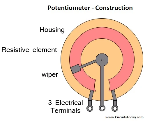
Figure 2: Cross-sectional view of potentiometer construction showing all major components
Main Components:
1. Resistive Element (Track)
The resistive element is the heart of the potentiometer. It's a conductive material deposited or wound in a specific pattern that provides resistance to current flow. Common materials include:
- Carbon Composition: Most common and economical. Made from carbon particles mixed with a binder, molded onto a phenolic substrate. Offers good reliability and moderate noise characteristics.
- Wire-wound: Made by winding resistance wire (such as nichrome) around an insulating core. Offers high power handling, excellent stability, and long life. Used in high-power applications and precision instruments.
- Conductive Plastic: Polymer-based material with excellent resolution and smooth motion. Can withstand millions of cycles with very low noise. Ideal for professional audio equipment.
- Cermet: Ceramic-metal composite offering exceptional stability, low temperature coefficient, and high-temperature tolerance. Common in trimmer potentiometers.
2. Wiper (Sliding Contact)
The wiper is a spring-loaded contact that slides along the resistive element. It's typically made from phosphor bronze or other conductive materials with good spring properties. The wiper must maintain consistent contact pressure to ensure reliable electrical connection while minimizing wear on the resistive track.
3. Shaft and Bushing
The shaft provides the mechanical interface for adjusting the potentiometer. It's connected to the wiper assembly and rotates (or slides) to move the wiper along the resistive element. The bushing (bearing) supports the shaft and allows smooth rotation while maintaining alignment.
4. Housing
The housing encloses and protects the internal components from dust, moisture, and mechanical damage. It also provides mounting features for securing the potentiometer to a panel or PCB.
5. Terminals
Three electrical terminals provide connection points: two for the ends of the resistive element and one for the wiper. These are typically solder lugs or PCB pins.
4. Potentiometer Circuit Symbol and Pinout
In circuit diagrams, potentiometers have specific symbols that indicate their function as variable resistors. Understanding these symbols is essential for reading schematics and designing circuits.
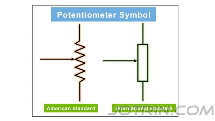
Figure 3: Potentiometer circuit symbols - American (ANSI/IEEE) and International (IEC) standards
Standard Symbols
There are two main standards for potentiometer symbols:
- American (ANSI/IEEE) Standard: Uses a zig-zag line to represent the resistor with an arrow pointing to the middle, indicating the wiper connection.
- International (IEC) Standard: Uses a rectangle to represent the resistor with an arrow pointing to one side, representing the wiper.
Both symbols show three terminals: two for the fixed ends of the resistive element and one for the movable wiper. The arrow indicates that the connection point is adjustable.
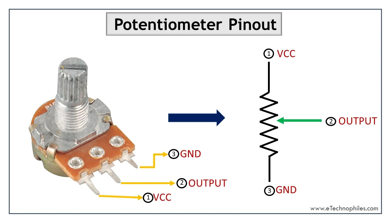
Figure 4: Potentiometer pinout - Terminal 1 (VCC), Terminal 2 (Output/Wiper), Terminal 3 (GND)
Pin Identification
Standard potentiometers have three pins that are typically numbered as follows:
| Pin Number | Name | Function |
|---|---|---|
| Pin 1 | Fixed End A | Connects to one end of the resistive element (typically VCC/Input) |
| Pin 2 | Wiper | Movable contact that provides variable output voltage |
| Pin 3 | Fixed End B | Connects to the other end of the resistive element (typically GND) |
5. Types of Potentiometers
Potentiometers come in various types, each designed for specific applications and mounting configurations. Understanding these types helps in selecting the right component for your project.
A. Rotary Potentiometers
Rotary potentiometers are the most common type. They feature a shaft that rotates to move the wiper along a circular (arc-shaped) resistive element. When you turn the knob on a radio or amplifier, you're using a rotary potentiometer.
Subtypes of Rotary Potentiometers:
1. Single-Turn Potentiometers
The most common type, offering approximately 270° to 300° of rotation from minimum to maximum resistance. Used in general applications like volume controls, brightness adjustments, and basic tuning.
2. Multi-Turn Potentiometers
Allow multiple rotations of the shaft (typically 3, 5, 10, or 20 turns) to achieve the full resistance range. Used for precision adjustments in calibration, instrumentation, and fine-tuning applications.
3. Dual-Gang Potentiometers
Two potentiometers mounted on a single shaft, allowing simultaneous adjustment of two channels. Commonly used in stereo audio equipment for left/right volume control.
4. Concentric Potentiometers
Two pots on the same axis with separate shafts (one inside the other), allowing independent control of two parameters. Used for simultaneous tone and volume control.
5. Motorized Potentiometers
Include an electric motor to drive the shaft, enabling remote or automated control. Used in audio mixers, remote volume controls, and automated systems.
B. Linear (Slide) Potentiometers
Linear potentiometers or slide pots have a straight resistive track, and the wiper moves linearly along it. These are commonly found in:
- Audio mixing consoles (faders)
- Graphic equalizers
- Joystick position sensing
- Industrial control panels
- Lighting dimmer boards
Linear pots can also be motorized for automated mixing applications and are available in single, dual, and multi-channel configurations.
C. Trimmer Potentiometers (Trimpots)
Trimmer potentiometers or presets are small potentiometers designed for mounting on PCBs. They're adjusted with a screwdriver and are intended for "set-and-forget" applications where occasional calibration is needed. Types include:
- Single-turn trimmers: Quick adjustment, coarse resolution
- Multi-turn trimmers: Fine adjustment with high resolution (cermet type)
- Surface-mount trimmers: Compact SMD packages for modern PCBs
Trimpots are used for calibrating sensor circuits, setting reference voltages, adjusting oscillator frequencies, and fine-tuning filter characteristics.
D. Digital Potentiometers (Digipots)
Digital potentiometers are integrated circuits that emulate the function of mechanical potentiometers using resistor ladders and electronic switches. They're controlled digitally via interfaces like SPI or I²C. We'll discuss these in detail in Section 9.
6. Understanding Potentiometer Taper (Linear vs Logarithmic)
The taper of a potentiometer describes how the resistance changes as you move the wiper. This characteristic is crucial for selecting the right pot for your application.
A. Linear Taper (Type B)
In a linear taper potentiometer, the resistance changes proportionally with the wiper position. If the wiper is at 50% of its travel, the resistance is 50% of the total value. This creates a straight-line relationship when graphed.
Characteristics of Linear Taper:
- Resistance changes uniformly with shaft rotation
- Marked with "B" or "LIN" on the potentiometer
- Output voltage is directly proportional to wiper position
- Most common and generally less expensive
Applications: Sensor calibration, instrumentation, motor speed control, power supply adjustment, and any application where proportional control is needed.
B. Logarithmic (Audio) Taper (Type A)
Logarithmic taper potentiometers change resistance exponentially rather than linearly. The resistance changes slowly at the beginning of the travel and more rapidly toward the end. This matches the logarithmic response of human hearing.
Characteristics of Logarithmic Taper:
- Resistance follows a logarithmic curve (exponential)
- Marked with "A" or "LOG" on the potentiometer
- Provides perceived uniform change in audio applications
- Approximately 10% of resistance change in the first 50% of rotation
Why use logarithmic for audio? The human ear perceives sound intensity logarithmically. A 10dB increase sounds like a "doubling" of volume regardless of the starting level. Using a linear pot for volume control would make most of the audible change happen in the first quarter of rotation, making fine adjustments difficult. Logarithmic pots provide a smooth, natural volume control experience.
Applications: Audio volume controls, gain controls in amplifiers, tone controls, and other applications matching human sensory perception.
C. Anti-Logarithmic (Reverse Audio) Taper (Type C)
Anti-logarithmic or inverse logarithmic taper is the opposite of logarithmic. Resistance changes rapidly at first, then slows down. Marked with "C" or "F" (anti-log), these are used in specialized applications like:
- Certain tone control circuits
- Applications where counterclockwise rotation should increase output
- Specific audio effect circuits
Taper Identification Chart
| Letter Code | Taper Type | Common Use |
|---|---|---|
| A | Logarithmic (Audio) | Volume controls, audio equipment |
| B | Linear | General purpose, sensors, motor control |
| C | Anti-Logarithmic | Specialized tone controls |
7. Wiring Configurations: Voltage Divider vs Rheostat
Potentiometers can be wired in different configurations depending on the desired function. The two primary configurations are the voltage divider (three-wire) and the rheostat (two-wire).
A. Voltage Divider Configuration (Three-Wire)
The voltage divider is the most common and fundamental way to use a potentiometer. All three terminals are utilized to create an adjustable output voltage.
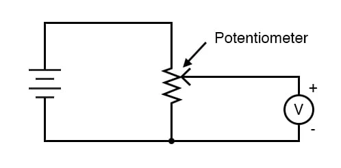
Figure 5: Potentiometer wired as a voltage divider with battery and voltmeter
How to Wire:
- Connect Terminal 1 to the positive voltage source (VCC)
- Connect Terminal 3 to ground (GND)
- Connect Terminal 2 (wiper) to your circuit's input
As you move the wiper, the output voltage at Terminal 2 varies from 0V (when at the GND end) to VCC (when at the VCC end). At the midpoint, you get VCC/2.
B. Rheostat Configuration (Two-Wire)
When used as a rheostat, the potentiometer functions as a simple variable resistor with only two terminals connected. This configuration controls current rather than voltage.
How to Wire:
- Connect Terminal 1 (or Terminal 3) to one side of your circuit
- Connect Terminal 2 (wiper) to the other side of your circuit
- Leave the unused end terminal unconnected (or connect it to the wiper for safety)
In this configuration, the resistance between the connected terminals varies from near-zero to the potentiometer's maximum rated resistance as you rotate the shaft.
Configuration Comparison
| Feature | Voltage Divider | Rheostat |
|---|---|---|
| Terminals Used | All 3 terminals | 2 terminals (wiper + one end) |
| Controls | Voltage | Current |
| Circuit Connection | Parallel with voltage source | Series with the load |
| Output | Variable voltage (0 to Vin) | Variable resistance (0 to Rmax) |
8. Common Applications of Potentiometers
Potentiometers are ubiquitous in electronics, finding applications across virtually every industry. Here are the most common uses:
A. Audio Equipment
- Volume Controls: Logarithmic pots provide smooth, natural volume adjustment in amplifiers, mixers, and consumer audio equipment
- Tone Controls: Bass, treble, and balance adjustments
- Gain Staging: Preamp gain control and input sensitivity adjustment
- Faders: Linear slide pots in professional mixing consoles
B. Consumer Electronics
- Television: Brightness, contrast, and color adjustment (in older models)
- Computer Monitors: Screen position and size controls
- Game Controllers: Joystick position sensing (thumbstick potentiometers)
- Toys: Speed and direction control in remote-controlled vehicles
C. Industrial and Automation
- Position Sensing: Linear and rotary pots measure displacement in machinery
- Process Control: Setpoint adjustment for temperature, pressure, and flow controllers
- Calibration: Trimpots for fine-tuning sensor circuits and reference voltages
- Motor Control: Speed reference input for variable frequency drives
D. Automotive
- Throttle Position Sensor (TPS): Monitors accelerator pedal position
- Climate Control: Temperature and fan speed adjustment
- Seat Position: Memory and adjustment systems
- Headlight Leveling: Automatic headlight angle adjustment
E. Test and Measurement
- Function Generators: Frequency and amplitude adjustment
- Oscilloscopes: Trigger level and position controls
- Power Supplies: Voltage and current limit adjustment
- Multimeters: Range selection and calibration
F. Lighting Control
- Dimmers: Incandescent and LED light dimming
- Stage Lighting: DMX controller faders
- Architectural Lighting: Brightness control in smart homes
G. Microcontroller Projects
- Analog Input: User interface knobs for Arduino, Raspberry Pi, and other platforms
- Sensor Simulation: Providing variable voltage for testing ADC circuits
- Menu Navigation: Scroll and selection controls
- Parameter Adjustment: Real-time tuning of control algorithms
9. Digital Potentiometers (Digipots)
Digital potentiometers (also called digipots or electronic potentiometers) are integrated circuits that emulate the function of mechanical potentiometers without any moving parts. They use resistor ladders and electronic switches controlled by digital signals.
How Digital Potentiometers Work
Inside a digipot, a string of resistors is connected in series between two terminals (A and B, equivalent to the ends of a mechanical pot). Electronic switches (typically CMOS transistors) connect various points along this resistor ladder to a third terminal (W, the wiper equivalent). A digital control circuit selects which switch to close, effectively moving the "wiper" to different positions.
Key Features of Digital Potentiometers:
- No Moving Parts: Solid-state design offers exceptional reliability and long life
- Digital Control: Controlled via SPI, I²C, or up/down interfaces
- Programmable: Resistance can be set and changed by software
- Non-volatile Options: Some digipots remember settings after power-off
- Multiple Channels: Single ICs can contain 1, 2, 4, or more independent pots
Control Interfaces
| Interface | Description | Example ICs |
|---|---|---|
| SPI | 4-wire serial (MOSI, MISO, SCLK, CS) | MCP41010, TPL0501, AD8400 |
| I²C | 2-wire with addressable devices | MCP4541, AD5242, DS1804 |
| Up/Down | Simple increment/decrement pulses | MCP4011, X9313 |
| Pushbutton | Direct button interface | Specialized interface ICs |
Resolution and Specifications
Digital potentiometers offer various resolutions, typically specified in "taps" or steps:
- 6-bit (64 steps): Basic adjustment
- 8-bit (256 steps): Common resolution, good for most applications
- 10-bit (1024 steps): High resolution for precision applications
Other important specifications include:
- End-to-End Resistance: Typically 1kΩ to 1MΩ (common: 5kΩ, 10kΩ, 50kΩ, 100kΩ)
- Tolerance: Usually ±10% to ±20% (precision types available to ±1%)
- Wiper Resistance: Typically 50Ω to 200Ω (adds series resistance)
- Voltage Range: Limited by supply voltage (typically 0-5V or ±15V for high-voltage types)
- Bandwidth: Depends on resistance value (higher R = lower bandwidth)
Applications of Digital Potentiometers
- Programmable Gain Amplifiers (PGA): Software-controlled amplification
- Programmable Filters: Adjustable cutoff frequencies
- LED Dimming: Microcontroller-controlled brightness
- Sensor Calibration: Automated trimming and compensation
- Remote Volume Control: Digitally controlled audio systems
- Closed-Loop Control: Automatic adjustment in feedback systems
10. How to Choose the Right Potentiometer
Selecting the appropriate potentiometer for your application requires considering several factors. Here's a comprehensive guide to help you make the right choice:
1. Determine the Resistance Value
Choose a resistance value that matches your circuit requirements:
- Audio circuits: 10kΩ to 100kΩ (50kΩ and 100kΩ are most common)
- Microcontroller ADC inputs: 10kΩ to 50kΩ (balances loading with noise immunity)
- High-current applications: Lower values (1kΩ or less) to minimize power dissipation
- High-impedance circuits: Higher values (100kΩ to 1MΩ)
2. Select the Taper Type
| Application | Recommended Taper |
|---|---|
| Volume control, audio gain | Logarithmic (Type A) |
| Sensor input, motor speed, general control | Linear (Type B) |
| Tone controls, specialized circuits | Anti-logarithmic (Type C) |
3. Choose the Physical Type
- Panel mounting: Rotary pots with knobs for user-adjustable controls
- PCB mounting: Smaller pots or trimmers for circuit board installation
- Slide pots: For faders and linear position applications
- Multi-turn: For precision calibration and fine adjustment
- Dual-gang: For stereo or multi-channel simultaneous control
4. Consider the Resistive Element Material
| Material | Best For | Avoid For |
|---|---|---|
| Carbon | General purpose, cost-sensitive | High precision, high power |
| Conductive Plastic | Professional audio, high resolution | High temperature, low cost |
| Cermet | Trimmers, stability, high temp | Smooth adjustment (can feel gritty) |
| Wire-wound | High power, precision instruments | Smooth control (stepped feel) |
5. Check Power Rating
Ensure the potentiometer can handle the power dissipation in your circuit. Standard potentiometers are typically rated from 0.1W to 2W. For higher power applications, consider:
- Wire-wound potentiometers (up to 100W+)
- Using the potentiometer as a control input rather than directly handling power
- Adding a power transistor or other driver circuit
Power Calculation Formula:
P = V² / R or P = I² × R
Always include a safety margin - operate at no more than 50-70% of the rated power.
6. Consider Environmental Factors
- Temperature range: Cermet and wire-wound handle high temperatures better
- Sealing: Sealed pots for dusty or humid environments
- Vibration: Wire-wound and cermet are more vibration-resistant
- Expected cycles: Conductive plastic lasts millions of cycles; carbon hundreds of thousands
Quick Selection Checklist
- ☐ What resistance value does my circuit need?
- ☐ Is this for audio (log) or general control (linear)?
- ☐ How will it be mounted (panel, PCB, etc.)?
- ☐ What power will it dissipate?
- ☐ How precise does the adjustment need to be?
- ☐ What is my budget?
- ☐ Any special environmental requirements?
Conclusion
Potentiometers are truly versatile components that form the backbone of countless electronic systems. From the simple volume knob on your radio to precision calibration equipment in industrial settings, understanding how a potentiometer works opens up endless possibilities for your electronics projects.
In this comprehensive guide, we've covered:
- The fundamental voltage divider principle that makes potentiometers work
- The construction and components that make up these devices
- Different types of potentiometers and their specific applications
- The importance of taper selection (linear vs logarithmic)
- Wiring configurations for voltage division and current control
- Wide-ranging applications across industries
- Modern digital potentiometer technology
- How to select the right potentiometer for your needs
Whether you're a beginner learning electronics or an experienced engineer designing complex systems, mastering potentiometers is essential. Their simplicity, reliability, and versatility make them indispensable tools in the world of electronics.
At FlyRobo, we offer a wide range of potentiometers including rotary, linear, trimmer, and digital types to suit all your project needs. Browse our collection to find the perfect component for your next electronics project!
Frequently Asked Questions (FAQs)
Q1: What is the difference between a potentiometer and a rheostat?
A potentiometer uses all three terminals and functions as an adjustable voltage divider. A rheostat uses only two terminals (wiper and one end) and functions as a variable resistor for current control. Any potentiometer can be used as a rheostat by leaving one terminal unconnected.
Q2: Why does my volume control use a logarithmic potentiometer?
Human hearing perceives sound intensity logarithmically. A logarithmic potentiometer provides a smooth, natural-sounding volume change that appears linear to our ears. Using a linear pot would make most of the volume change happen in the first quarter of rotation.
Q3: Can I use a potentiometer to control motor speed?
For small DC motors, you can use a potentiometer as a rheostat in series with the motor. However, this is inefficient as excess power is dissipated as heat. For better control, use the potentiometer as a voltage divider to provide a control signal to a motor driver circuit or PWM controller.
Q4: How do I identify the pins on a potentiometer?
Use a multimeter in resistance mode. Measure between pairs of pins while rotating the shaft. The resistance between the two outer pins should remain constant (the total resistance). The resistance between either outer pin and the middle pin will change as you rotate - these are your wiper connections.
Q5: What happens if I exceed the power rating of a potentiometer?
Exceeding the power rating will cause overheating, which can damage the resistive element, cause the wiper to lose contact, or permanently change the resistance value. In extreme cases, it can cause the potentiometer to burn out or fail completely. Always include a safety margin in your design.
Q6: Can I replace a mechanical potentiometer with a digital one?
Yes, but with considerations. Digital potentiometers have voltage and current limitations, wiper resistance, and bandwidth constraints. They're excellent for signal-level applications but cannot directly replace mechanical pots in high-power or high-voltage applications. Check the datasheet carefully before substituting.
Related Products at FlyRobo
Looking for potentiometers for your next project? Check out our extensive collection:
- Rotary Potentiometers - 1kΩ to 1MΩ in linear and logarithmic tapers
- Slide Potentiometers - Perfect for audio mixers and fader applications
- Trimmer Potentiometers - Single-turn and multi-turn for PCB calibration
- Digital Potentiometer Modules - SPI and I²C controlled for Arduino and Raspberry Pi
- Potentiometer Kits - Assorted values for your workshop
Visit www.flyrobo.in to explore our full range of electronic components!

Leave a Comment