
Hello,
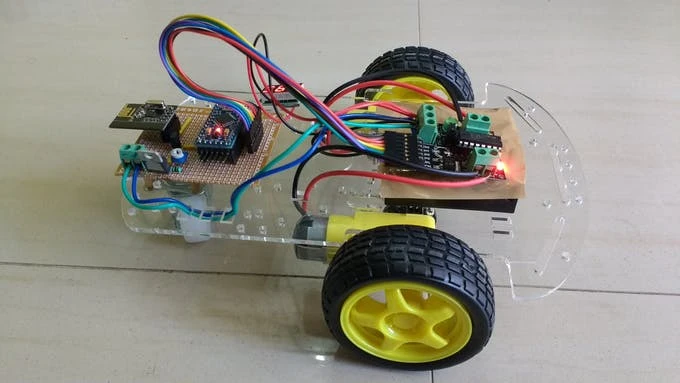
In this tutorial, we are going to build a car using nRF module and Arduino pro mini.
Hardware Required
Software Required
A car is a very common project in the Arduino world. It is one of the simplest projects. But today we are going to add some complexities to it. But first let us learn in brief about the nRF modules and Arduino pro mini.
Arduino Pro mini is a small but quite powerful board. It is very similar to the Arduino Uno as they use the same processor. It is even more versatile than Uno as it has a small size and so it can be used in permanent embedded systems projects.
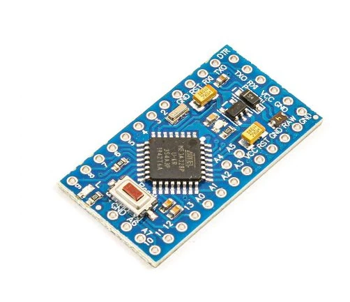
Arduino Pro Mini Pinout
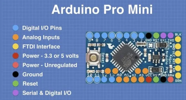
One of the advantages the Arduino pro mini has over the Uno is that it can have two additional analog input/output pins. This is mainly possible as the pro mini pins are surface mount whereas the Uno pins use female headers. The pro mini also has a both 5V and 3.3V pins. But for all these advantages, the Arduino Pro mini has a big disadvantage over the Uno. It does not contain any USB ports to connect it directly to a computer. Thus, it requires a device called as an FTDI adapter to connect it to a computer.
FTDI Adapter
FTDI is the short form of the semiconductor manufacturer Future technology devices International. In addition to FTDI adapters, this company also makes different sorts of video adapters. It has one mini USB port on one side and 6 male header pins on the other side.
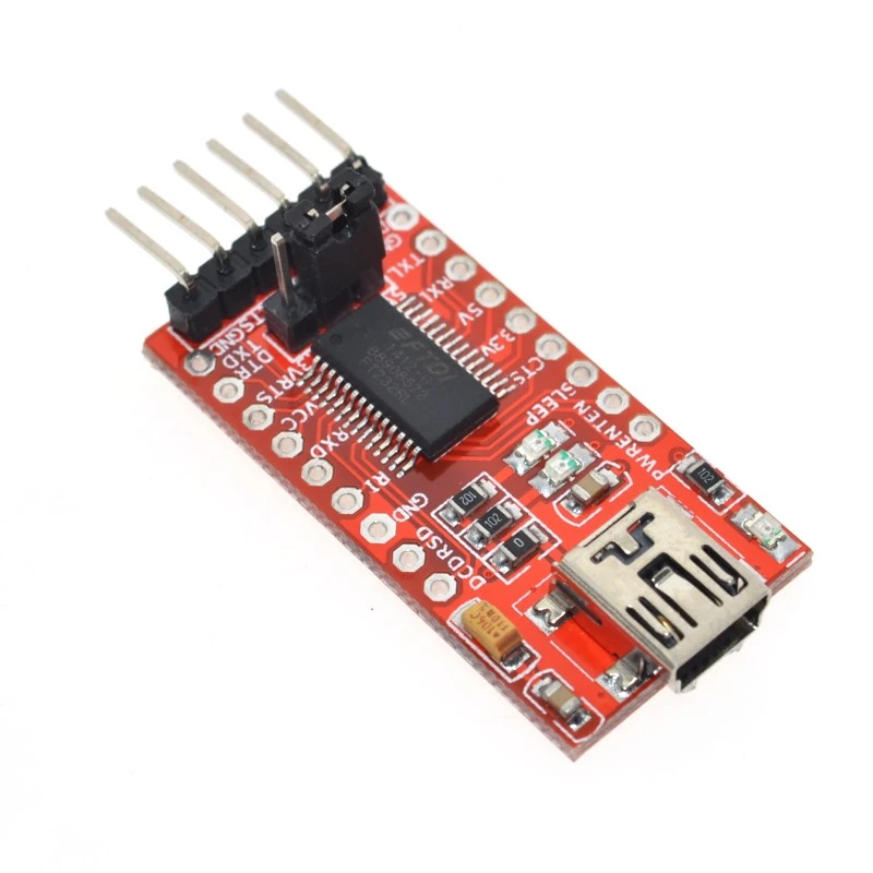
The FTDI adapter not only provides pins for data transfer, but it also provides pins for power supply to the Arduino board.
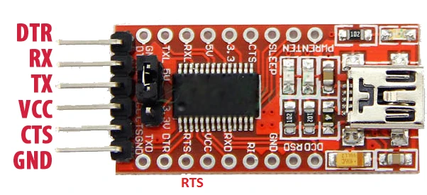
As Arduino mini has both 3.3V and 5V pins. And the FTDI adapter can supply both 3.3 and 5 volts but to select the voltage, we need to connect a jumper on the FTDI board. But you need to be careful about this. You cannot connect a 5V jumper and then connect the VCC pin to 3.3V. This can damage the Arduino board. So connect the jumpers properly.
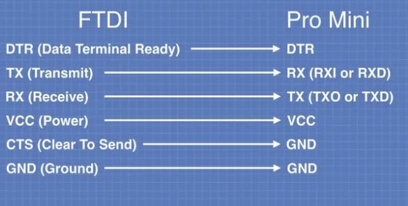
The connections from the FTDI to the pro mini board are listed as follows:
- DTR- This pin is short for Data Terminal Ready. This pin sends a signal from the FTDI to the pro mini stating it is ready to send the data.
- TX- To transmit the data to the Arduino board.
- RX- To receiver the data from the Arduino board.
- VCC- Power supply pin. It can provide both 3.3 and 5 volts depending upon the jumper.
- GND- Ground pin.
- CTS- Clear to send pin. This means Arduino board will send the signal to FTDI adapter stating it is ready to receive the data.
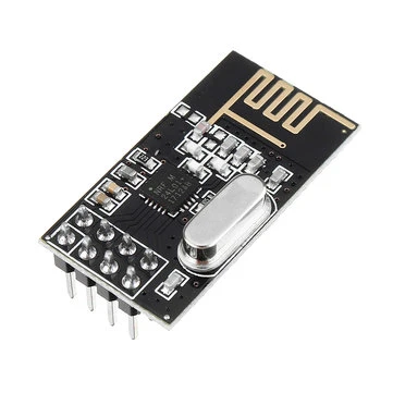
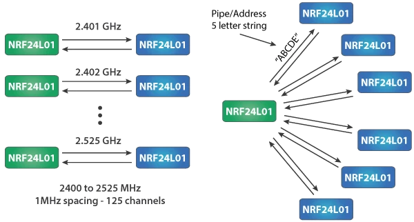
The nRF transceiver module is a 2.4 GHz band module and it operates on the baud rates between 250 Kbps and 2 Mbps. In an open space, the lower baud rates can give out a range upto 100 meters. The nRF module offers a 125 different channels which means there are 125 different modem setups possible. And a single channel can hold upto six addresses. This means that each nRF module can connected and send data to another six nRF modules on a single channel.
The operating current of the nRF module is around 12 mA when transmitting which is lower than a working LED. The operating voltage of the nRF module is 1.9 to 3.6 volts. But the pins can tolerate 5 volts so it can easily be used with Arduino pins.
![]()
The nRF module uses SPI communication protocol for interfacing with Arduino. So there are three SPI pins: MISO, MOSI and SCK situated on the nRF module. The detailed specifications of the nRF module are listed below.
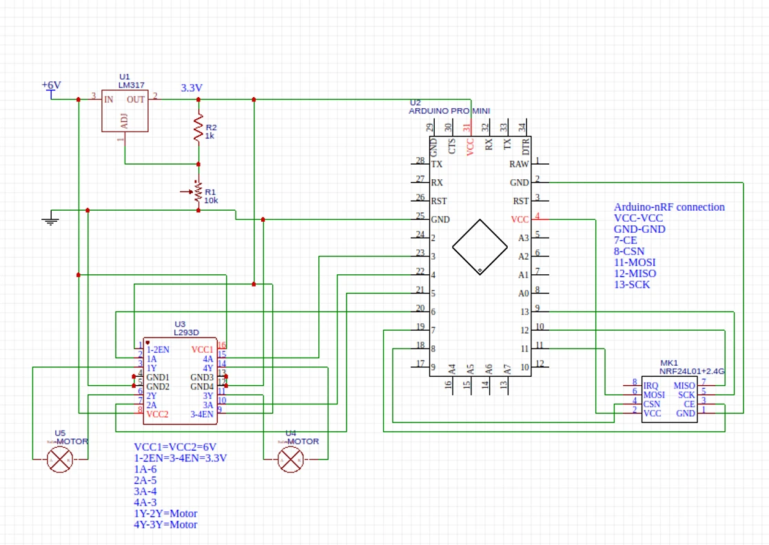
Circuit Diagrams
- Transmitter side
![]()
- Receiver side
Working concept
- The working concept for this project is quite tedious as it involves two different circuits. The process starts when the user pushes one out of the four pushbuttons. This sends the command to the Arduino on the transmitter side.
- The Arduino then sends the appropriate command to the nRF module transmitter.
- The receiver nRF module receives the command on the car. It further sends the command to the Arduino board on the car.
- The Arduino then rotates the motor according to the commands received. This results in movement of the car.
Arduino Code
- Transmitter side (remote)
#INCLUDE#INCLUDE RF24 RADIO(7,8); CONST BYTE ADDRESS[6] = "00001"; CONST INT FRONTBUTTON = 6; CONST INT BACKBUTTON = 5; CONST INT LEFTBUTTON = 4; CONST INT RIGHTBUTTON = 3; VOID SETUP() { PINMODE(FRONTBUTTON,INPUT_PULLUP); PINMODE(BACKBUTTON,INPUT_PULLUP); PINMODE(LEFTBUTTON,INPUT_PULLUP); PINMODE(RIGHTBUTTON,INPUT_PULLUP); SERIAL.BEGIN(9600); RADIO.BEGIN(); SERIAL.PRINTLN("CHECKING IF CHIP CONNECTED"); BOOL CHECK = RADIO.ISCHIPCONNECTED(); SERIAL.PRINT("CHECK-"); SERIAL.PRINTLN(CHECK); RADIO.OPENWRITINGPIPE(ADDRESS); RADIO.SETPALEVEL(RF24_PA_HIGH); RADIO.STOPLISTENING(); } VOID LOOP() { INT MESSAGE[4]; MESSAGE[0] = DIGITALREAD(FRONTBUTTON); MESSAGE[1] = DIGITALREAD(BACKBUTTON); MESSAGE[2] = DIGITALREAD(LEFTBUTTON); MESSAGE[3] = DIGITALREAD(RIGHTBUTTON); SERIAL.PRINTLN("TRANSMITTED"); RADIO.WRITE(&MESSAGE,SIZEOF(MESSAGE)); DELAY(100); //YOU CAN PLAY WITH THIS NUMBER }
- Receiver side
#INCLUDE#INCLUDE RF24 RADIO(7, 8); CONST BYTE ADDRESS[6] = "00001"; CONST INT IN1 = 6; CONST INT IN2 = 5; CONST INT IN3 = 4; CONST INT IN4 = 3; VOID SETUP() { PINMODE(IN1,OUTPUT); PINMODE(IN2,OUTPUT); PINMODE(IN3,OUTPUT); PINMODE(IN4,OUTPUT); SERIAL.BEGIN(9600); RADIO.BEGIN(); SERIAL.PRINTLN("CHECKING IF CHIP CONNECTED"); BOOL CHECK = RADIO.ISCHIPCONNECTED(); SERIAL.PRINT("CHECK-"); SERIAL.PRINTLN(CHECK); RADIO.OPENREADINGPIPE(0, ADDRESS); RADIO.SETPALEVEL(RF24_PA_MIN); RADIO.STARTLISTENING(); } VOID LOOP() { IF (RADIO.AVAILABLE()) { INT MESSAGE[4]; RADIO.READ(&MESSAGE, SIZEOF(MESSAGE)); INT I; FOR (I = 0; I < 4; I = I + 1) { SERIAL.PRINT(MESSAGE[I]); } SERIAL.PRINTLN(); INT SUM = MESSAGE[0]+MESSAGE[1]+MESSAGE[2]+MESSAGE[3]; IF (SUM==4) { DIGITALWRITE(IN1,LOW); DIGITALWRITE(IN2,LOW); DIGITALWRITE(IN3,LOW); DIGITALWRITE(IN4,LOW); SERIAL.PRINTLN("LLLL"); } IF (SUM==3) { IF (MESSAGE[0]==0 && MESSAGE[1]==1 && MESSAGE[2]==1 && MESSAGE[3]==1) { DIGITALWRITE(IN1,HIGH); DIGITALWRITE(IN2,LOW); DIGITALWRITE(IN3,LOW); DIGITALWRITE(IN4,HIGH); SERIAL.PRINTLN("HLLH"); } IF (MESSAGE[0]==1 && MESSAGE[1]==0 && MESSAGE[2]==1 && MESSAGE[3]==1) { DIGITALWRITE(IN1,LOW); DIGITALWRITE(IN2,HIGH); DIGITALWRITE(IN3,HIGH); DIGITALWRITE(IN4,LOW); SERIAL.PRINTLN("LHHL"); } IF (MESSAGE[0]==1 && MESSAGE[1]==1 && MESSAGE[2]==0 && MESSAGE[3]==1) { DIGITALWRITE(IN1,LOW); DIGITALWRITE(IN2,LOW); DIGITALWRITE(IN3,LOW); DIGITALWRITE(IN4,HIGH); SERIAL.PRINTLN("LLLH"); } IF (MESSAGE[0]==1 && MESSAGE[1]==1 && MESSAGE[2]==1 && MESSAGE[3]==0) { DIGITALWRITE(IN1,HIGH); DIGITALWRITE(IN2,LOW); DIGITALWRITE(IN3,LOW); DIGITALWRITE(IN4,LOW); SERIAL.PRINTLN("HLLL"); } } IF (SUM<=2) { DIGITALWRITE(IN1,LOW); DIGITALWRITE(IN2,LOW); DIGITALWRITE(IN3,LOW); DIGITALWRITE(IN4,LOW); SERIAL.PRINTLN("LLLL"); } } }


Leave a Comment