11 Oct

Hello,
In this tutorial, we are going to build a mini-lift using Arduino.
Hardware Required
Software Required
- Many of the workshops have only one downside: they have two different floors. So the movement of large components is very difficult. And the installation of an elevator is also difficult. So we decided to go with a mini-lift. This is perfect for the movement of components and parts. We can also make this lift wireless to operate by either adding Bluetooth or Wi-Fi to this setup.
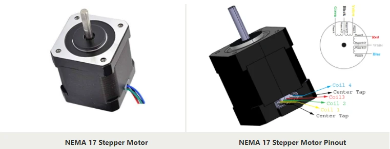
- NEMA17 Stepper motor is hybrid stepper motor which has 200 steps per revolution. It has 4 phases and each phase uses 1.2A at 4 volts. It is highly precise motor and is generally used in 3D printers, CNC machines and laser cutting machines.
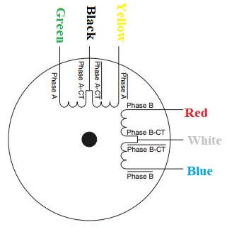
- The NEMA17 stepper motor has a unipolar six-wire arrangement. There are two windings. The green, black and yellow are the first winding and the black is the center tap. The red, white and the blue colors belong to the second winding where white is the center tap and red and blue are the endings of the coil. Usually center tap wires are disconnected.
- So the stepper motor is connected to the motor driver via 4 pins only (coil endings).
Circuit Diagram
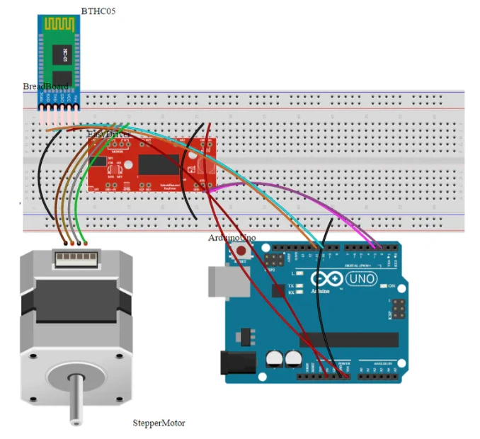
- The Bluetooth module HC-05 has 4 pins: TX, RX, VCC and GND. The TX and RX pins are connected to the Digital pins 11 and 10 of the Arduino respectively. VCC and GND are connected to the 5V and GND pins respectively.
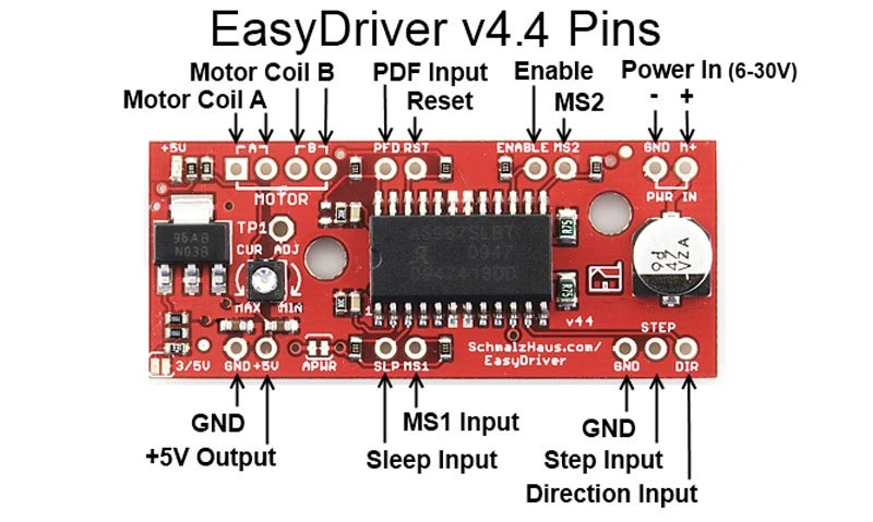
- Stepper motor has 4 pins: 1A, 2A, 1B, 2B. The A pins are connected to the motor coil A pins on the stepper motor driver. The B pins are connected to the motor coil B pins on the stepper motor driver. The Power In pins are connected to the power pins on the Arduino board.
Working concept
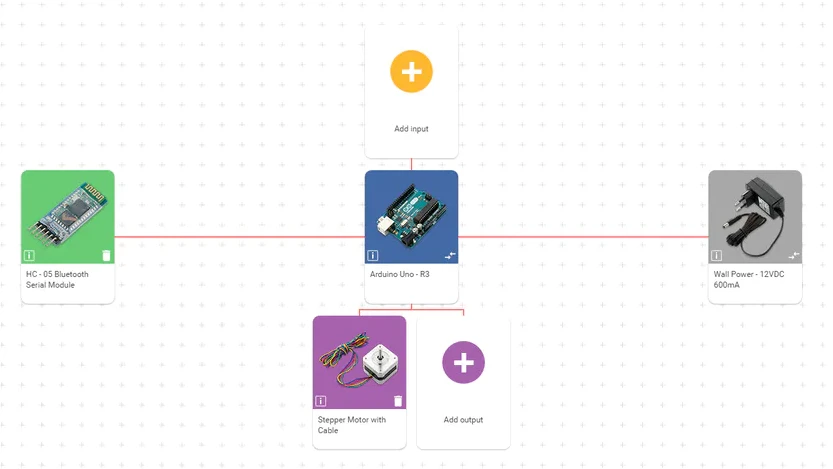
- The working concept involves 4 different components: HC-05 Bluetooth module, Arduino Uno, Stepper driver and Stepper motor.
- The command is sent via the application on the smartphone to the HC-05 module.
- The Bluetooth module then sends those commands to the Arduino board. The board then processes those commands and sends the appropriate signals to the A3967 stepper driver.
- The stepper driver, upon receiving the commands from the Arduino board, will rotate the motor by the amount of steps and direction required.
- This whole process is repeated once a new command is sent from the application.
Arduino Code
#include "Arduino.h"#include "BTHC05.h"#define BTHC05_PIN_RXD 10#define BTHC05_PIN_TXD 11#define STEPPER_PIN_STEP 2#define STEPPER_PIN_DIR 3const int stepPeriod = 300;const int liftHeightInSteps = 10000;BTHC05 bthc05(BTHC05_PIN_RXD, BTHC05_PIN_TXD);void setup() {Serial.begin(9600);Serial.println("start");pinMode(STEPPER_PIN_STEP, OUTPUT);pinMode(STEPPER_PIN_DIR, OUTPUT);bthc05.println("Bluetooth On....");}void loop() {String bthc05Str = "";if (bthc05.available()){bthc05Str = bthc05.readStringUntil('\n');Serial.print("BT Raw Data: ");Serial.println(bthc05Str);}if (bthc05Str == "u"){moveStepper(liftHeightInSteps, 1, stepPeriod );}if (bthc05Str == "d"){moveStepper(liftHeightInSteps, 0, stepPeriod );}}void moveStepper(int steps, bool dir, int timePeriod){digitalWrite(STEPPER_PIN_DIR, dir);for (int i = 0 ; i < steps ; i++){digitalWrite(STEPPER_PIN_STEP, HIGH);delayMicroseconds(timePeriod);digitalWrite(STEPPER_PIN_STEP, LOW);delayMicroseconds(timePeriod);}}
- Upload the code to the Arduino board.
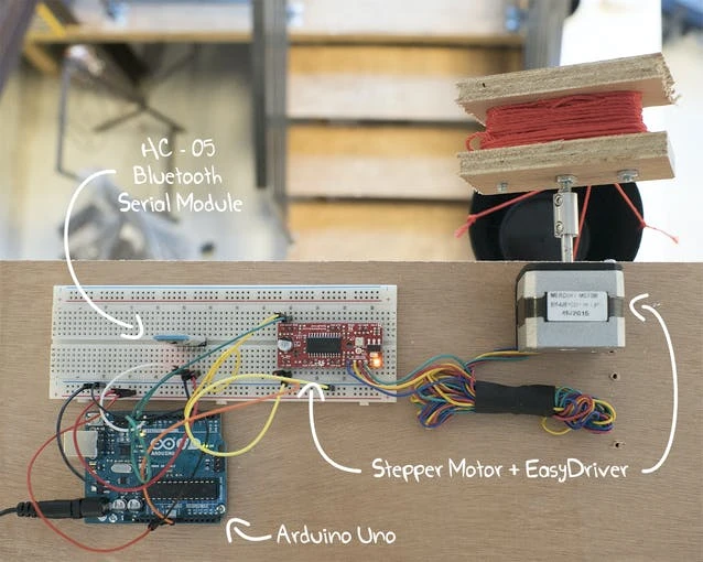
- The Final setup will look like this
- The below video shows the working of the project.
- I hope you learned something about this project with the help of this tutorial. Thank you.

Hot
-59 %
The Arduino Uno R3 Compatible board is an electronic hardware device used to build and program electronic circuits and projects. The board is based on..
₹528 ₹1,299

-40 %
HC-05 is a Bluetooth Transceiver Module and has TTL Output. HC-05 6 Pin Wireless Serial Bluetooth Module is a Bluetooth module for use with any microc..
₹298 ₹499

This is 40pcs of each (40 M-M, 40 M-F, 40 F-F) jumper cable Dupont wire for Arduino.
Specifications:
This is 40 pcs of each (total 120 pcs)..
₹159

Out Of Stock
The NEMA17 4.2 kg-cm Stepper Motor can provide 4.2 kg-cm of torque at 1.2A current per phase. The stepper motors move in precisely repeatable steps, h..
₹753

-37 %
A3967 Stepper Motor Driver Board provides greater flexibility and control over the stepper motor. This stepper motor driver is compatible with most mi..
₹175 ₹279

Leave a Comment