26 Dec
-1060x400h.webp "Ultrasonic tripwire alarm")
Hello,
In this tutorial, we are going to learn how to make an ultrasonic tripwire alarm using Arduino.
Hardware Required
Software Required
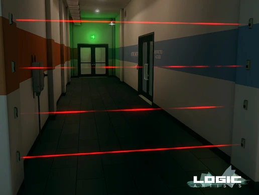
- No security system is complete without a tripwire alarm. These alarms are generally made with the help of lasers. So if anyone or anything cuts the laser off, an alarm starts ringing. It can be a standalone system or can be a part of a much bigger security system in a network of tripwire alarms.
- Now let us look deeper into the process of interrupting the laser beam. Whenever the laser beam is interrupted, the resistance of the photoresistor increases dramatically. This increases the voltage dramatically and as soon as this happens the alarm is buzzed.
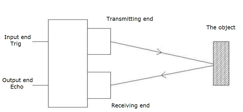
- In this project, we are going to do things differently. Instead of using a laser beam and a photoresistor, we are going to use an ultrasonic distance measuring module. The ultrasonic sensor HC-SR04 works on the principle of sonar. It has a transmitter and a receiver which is in-built inside the sensor.
Working concept
- The working concept of the ultrasonic tripwire alarm is quite different from that of laser tripwire alarms. In the case of laser tripwires, the alarm is buzzed whenever the resistance and the voltage of the photoresistor are increased drastically. This only happens when the laser beam, which is falling onto the photoresistor, is interrupted.
- The working of this ultrasonic tripwire is completely different. The sensor emits ultrasonic waves continuously wherever it is placed. At first, the sensor calculates the distance at which the object in front of it is going to stay. It might be a wall or anything else.
- After calculating this distance, it is stored inside the program. Now as soon as anything interrupts this wave, it will get reflected back early towards the receiver. And it will calculate that the distance has been decreased. As soon as this happens, the ultrasonic sensor will send a signal to the Arduino board.
- The Arduino board upon receiving the signal will send the signal further to the piezoelectric buzzer to ring.
- This completes the working concept of this project.
Circuit Diagram
.webp)
|
Pins on Arduino Uno |
Pins on HC-SR04 |
|
5V |
VCC |
|
GND |
GND |
|
D9 |
TRIG |
|
D10 |
ECHO |
- Piezoelectric buzzer GND pin is connected to GND on Arduino board and the positive terminal is connected to digital pin 3 on the Arduino board.
Arduino code
#define trigPin 9 #define echoPin 10 long duration; int distance; long firstoff; int distancefirst; void setup() { Serial.begin(9600); pinMode(trigPin, OUTPUT); pinMode(echoPin, INPUT); delay(1000); digitalWrite(trigPin, HIGH); delayMicroseconds(10); digitalWrite(trigPin, LOW); firstoff = pulseIn(echoPin, HIGH); distancefirst = firstoff*0.034/2; } void loop() { digitalWrite(trigPin, LOW); delayMicroseconds(2); digitalWrite(trigPin, HIGH); delayMicroseconds(10); digitalWrite(trigPin, LOW); duration = pulseIn(echoPin, HIGH); distance= duration*0.034/2; Serial.println(distance); delay(1000); Serial.println(distancefirst); if (distance <= distancefirst - 5) { tone(3, 500, 500); delay(500); tone(3, 800, 500); delay(500); delay(50); } }
- Upload the code. Perform the circuit diagram.
Now your Ultrasonic tripwire alarm is ready to go.

-73 %
The Arduino Nano is a small, complete, and breadboard-friendly board based on the ATmega328 (Arduino Nano 3.x) or ATmega168 (Arduino Nano 2.x). It has..
₹205 ₹756

-8 %
This HC-SR04-Ultrasonic Distance Measuring Sensor is a very popular sensor which is found in many applications where it requires to measure distance a..
₹82 ₹89

This is 40pcs of each (40 M-M, 40 M-F, 40 F-F) jumper cable Dupont wire for Arduino.
Specifications:
This is 40 pcs of each (total 120 pcs)..
₹159

-8 %
This is a general-purpose continuous Piezo Electric Buzzer Alarm. It works from 3 to 12 V.
It has two mounting holes and can be easily mounted to ..
₹54 ₹59

Leave a Comment