-1060x400h.webp "Remote controlled car with ESP32-cam")
Hello,
In this tutorial-based article, we will learn more about the ESP32cam module and we will use it to make a remote-controlled car using Wi-Fi.
What is the ESP32-CAM module?
-
The ESP32-CAM is a normal microcontroller based on the ESP32 structure and it also contains a slot for a MicroSD card and an integrated camera. It’s very economical and easy to operate and is perfect for IoT devices requiring a camera with advanced functions like image tracking and recognition.
The architecture of the ESP32-CAM module
-
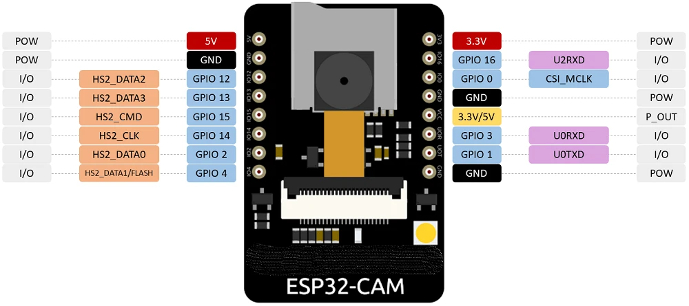
The ESP32-CAM module has lesser input and output pins than the ESP-32 module on which it is based. Most of the GPIO pins are used for the microSD card port and the camera.
The thing which is missing from the ESP32-CAM module is the USB port to upload the code. In this project, we are going to use the CP2102 USB to UART module to upload the code to ESP32-CAM. -
This module has printed circuits on both sides. On the top, the board has the connector for the camera module. It also has a slot for a microSD card on the top.
-
On the bottom of the board, there is a reset switch that is used to reset the program uploaded from the software
-
As we know, ESP32-CAM shares the same structure as the ESP32-S. So the specifications of both the boards are almost the same.
-
802.11b/g/n Wi-Fi.
-
Bluetooth 4.2 with BLE.
-
The clock speed is up to 160 MHz.
-
Computing power up to 600 DMIPS.
-
520 KB SRAM plus 4 MB PSRAM.
-
Supports Wi-Fi Image upload.
-
Multiple sleep modes.
-
Firmware over the air (FOTA) upgrades are possible.
-
9 GPIO ports.
-
Built-in flash LED.
Camera specifications
-
The image transfer rate of this module is 15-60 fps.
-
Output formats for this module include YUV422, YUV420, RGB565, RGB555, and 8-bit compressed data
-
Array size UXGA 1622 x 1200
-
Camera sensor of 2 Megapixel
Uploading the code to ESP32-cam
-
The ESP32-cam module has no USB port. So you cannot just connect it to your computer and upload programs onto it.
-
To upload the code, you need to connect the esp32 to an external FTDI adapter.
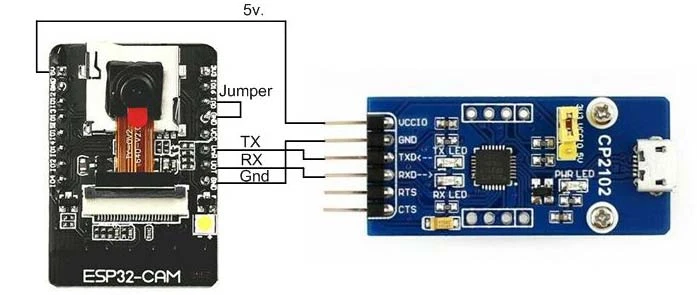
-
Make sure your Arduino software is up to date. Open the Arduino IDE.
-
Choose the File menu on the top menu bar.
-
Look for the preferences menu and click on it.
-
Look for the textbox labeled “Additional Boards Manager URLs”.
-
If you already have a link in the text box, then add a comma to it. Now paste the following link in the text box: https://raw.githubusercontent.com/espressif/arduino-esp32/gh-pages/package_esp32_index.json
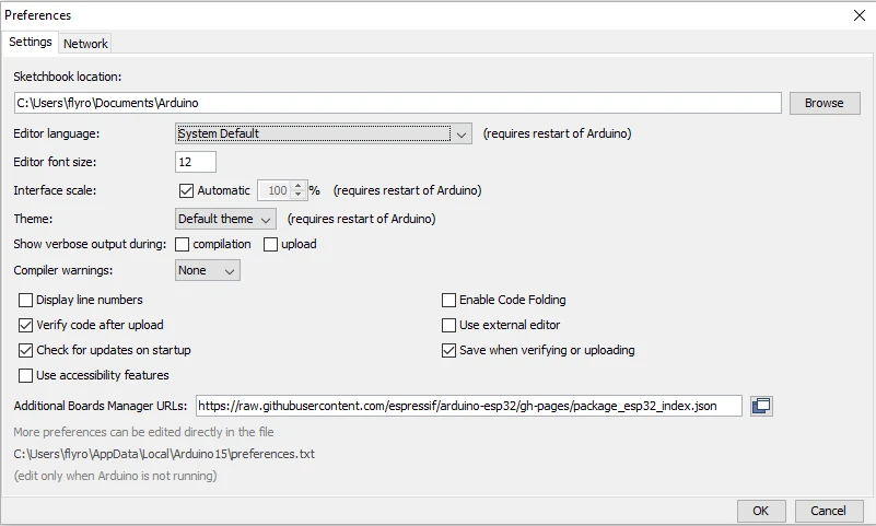
-
Click on OK. This will save the settings which you have changed.
Hardware required
Software required
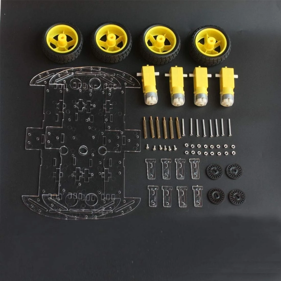
Car chassis and motors
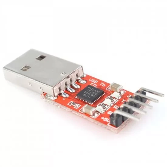
CP2102 USB to TTL module
-
CP2102 module is a USB to UART converter module. It requires minimal external components. CP2102 can be used to connect devices to computers via USB.
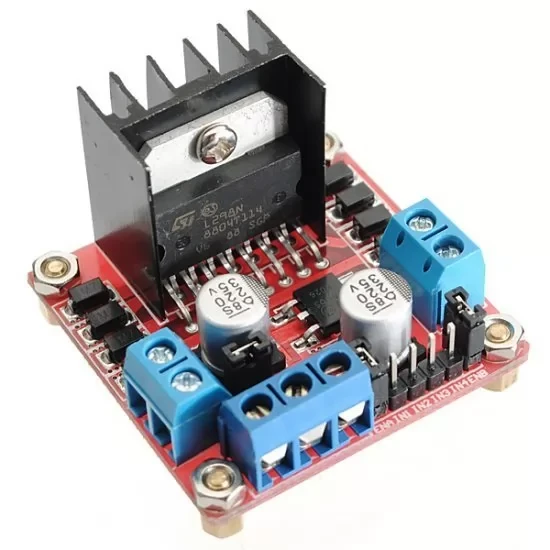
L298N motor driver
-
L298N motor driver is perfect for driving DC motors and Stepper motors. It can control 4 DC motors or 2 DC motors with direction and speed control. This motor driver is perfect for robotics projects and perfect for controlling motors from microcontrollers. Perfect for driving DC stepper motors for micro line-follower robots, robot arms, etc.
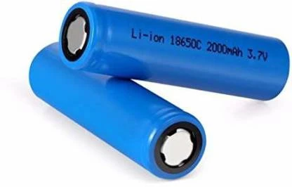
Li-ion battery
-
18650 is a single cell, compact and powerful cell with a 2200 mAh capacity. It is very convenient to fulfill the 3.7 Volt requirement with this cell. The battery terminals can use in any compatible battery adapter/holder or they can be permanently soldered to your application's power source wires.
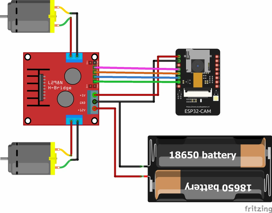
Circuit Diagram
|
Pins on L298N motor driver |
Pins on the ESP32 Camera module |
|
IN1 |
GPIO 2 |
|
IN2 |
GPIO 14 |
|
IN3 |
GPIO 15 |
|
IN4 |
GPIO 13 |
|
5V |
5V |
|
GND |
GND |
-
Connect the positive terminal of the battery to 12V and the negative terminal to GND.
-
Connect the two motors on the right side together and same with the left side. Now both the motors on the right side will move together.
-
Now connect the two terminals of motors on the right side with pins Out 1, 2 on the motor driver. Similarly, connect the two motors of the left side on pins Out 3, 4.
The working concept of the Remote controlled car
-
ESP32-camera module works on Wi-Fi. So it can be given commands wirelessly via IP address.
-
As the command is given from an internet browser with the same IP address, the ESP32 then gives the command to the motor driver.
-
The motor driver then turns the motors which translate into motion.
-
Simultaneously, the ESP32-camera module can stream the video from the camera back to the browser via Wi-Fi.
Arduino Code
-
The code for remote controlled car using ESP32-camera can be downloaded here. >
Uploading the code for a remote-controlled car
Now your remote-controlled car is ready for use. Enjoy!
-
First, perform the steps given above to add ESP32 boards to your Arduino IDE.
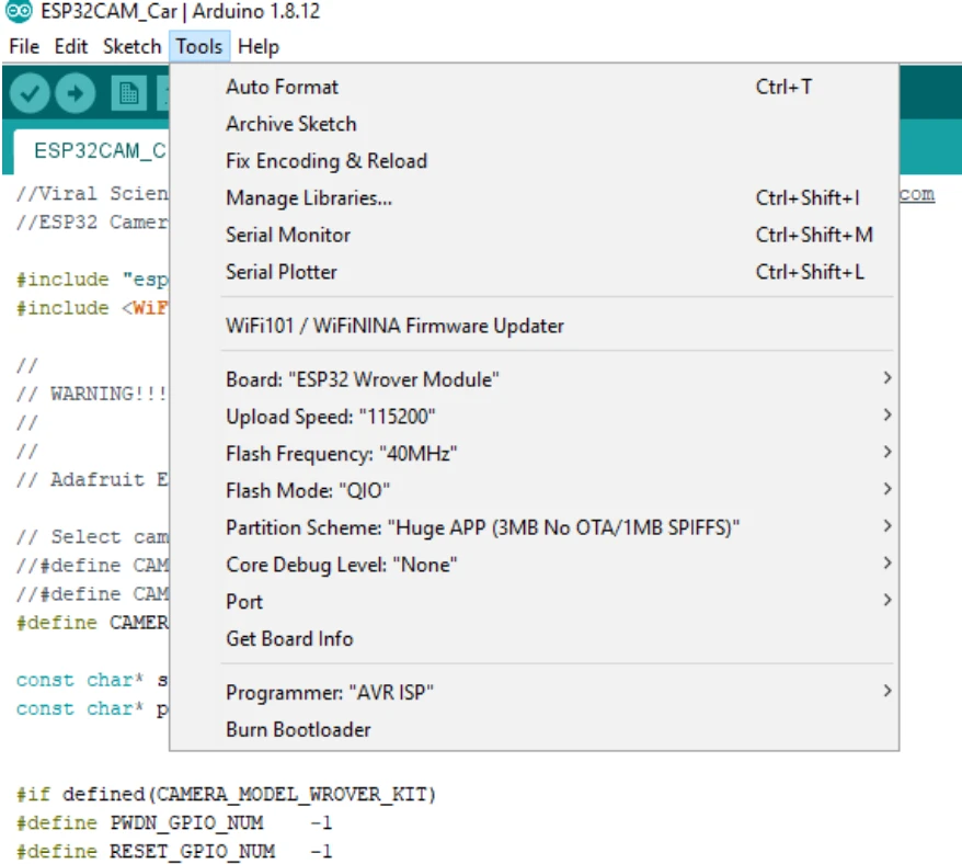
-
Now go to tools. Set the values according to the given picture below.
-
Upload the code using the circuit diagram given for ESP32-cam and CP2102. Press the reset button on ESP32 if there is an error in uploading the code.
-
After uploading the code, remove the shorted pins IOO and GND.
-
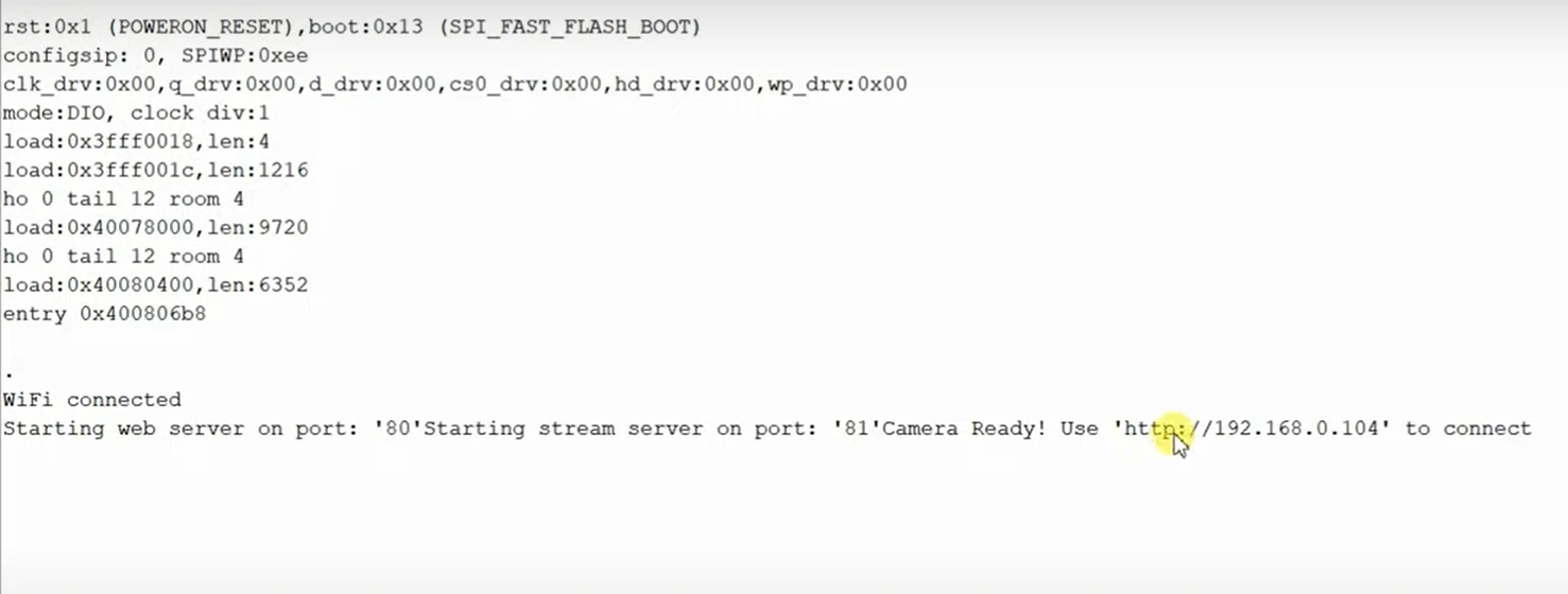
Now open the Serial Monitor on Arduino IDE and press the reset button on ESP32.
-
A window like this will appear. Wait for it to say Wi-Fi connected.
-
Once the ESP32 is connected to Wi-Fi, copy the IP address and open it in the browser of your device.
-
Now you can control the car remotely. You can also watch the live feed from the ESP32 camera and turn on/off the flash too.


(Restock: 16-08-2026 to 20-08-2026)
 USB to TTL UART serial converter Module")


Leave a Comment