04 Feb

Hello,
In this tutorial, we are going to build an automatic leveler using Arduino and an accelerometer.
Hardware Required
Software Required
- Today we are going to look at an interesting project. The automatic leveler uses an accelerometer to detect the inclination and uses a gimbal to the the floor levelled. First let us understand how the accelerometer works.
- An accelerometer is a tool which measures the vibration, motion or acceleration of a structure. Cameras and smartphones these days use an accelerometer consisting of an axis-based motion sensor. It is an electromechanical device which measures either static or dynamic acceleration. Acceleration, as we know, is the measure of change in velocity upon given time.
- Accelerometers are used in the compass app you use on your phone. The motion sensors in accelerometers have the ability to detect earthquakes too. Another example is when the accelerometers measure the gravitational pull to determine at which angle is the device being titled.
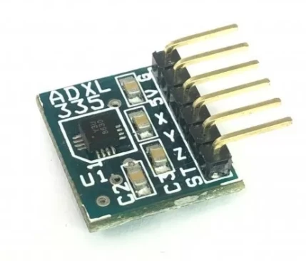
Working principle of the accelerometer ADXL335
- There are generally two types of capacitive accelerometers right now. One is MEMS (Micro electro mechanical sensor). MEMS generally have a silicon based material with a mass attached to it and it is integrated into a circuit. As the acceleration is applied, the mass moves and thus the silicon material also moves. This creates a charge in the circuit. The charge is used to calculate the acceleration.
- The other type is analog accelerometers. They work on two different principles which we discuss above: piezoelectric sensing and capacitive sensing. ADXL335 works on the principle of capacitive.
- ADXL335 is a capacitive accelerometer. It works on the principle that when the acceleration is applied to the sensor, the capacitance inside the sensor changes. This change in capacitance is then used to measure the acceleration of the object.
- This is a 3-axis accelerometer. So it can be used to calculate all the accelerations in three-dimensions.
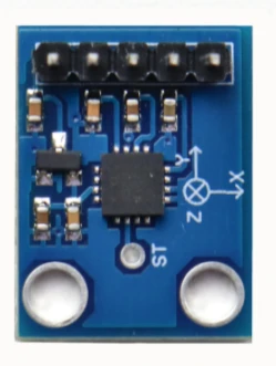
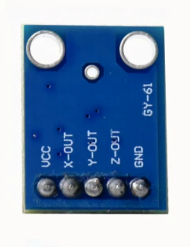
- The ADXL335 sensor has 6 pins and an integrated chip on the front of the board. The pins are soldered at the back of the board.
- VCC pin is used for the power supply.
- X-out is the output to measure the acceleration along the x-axis.
- Y-out is the output to measure the acceleration along y-axis.
- Z-out is the output to measure the acceleration along z-axis.
- GND is the ground pin
- ST pin located above the integrated chip is the self test feature. This self test feature allows us to check the functioning of the accelerometer in the final model.
Circuit Diagram
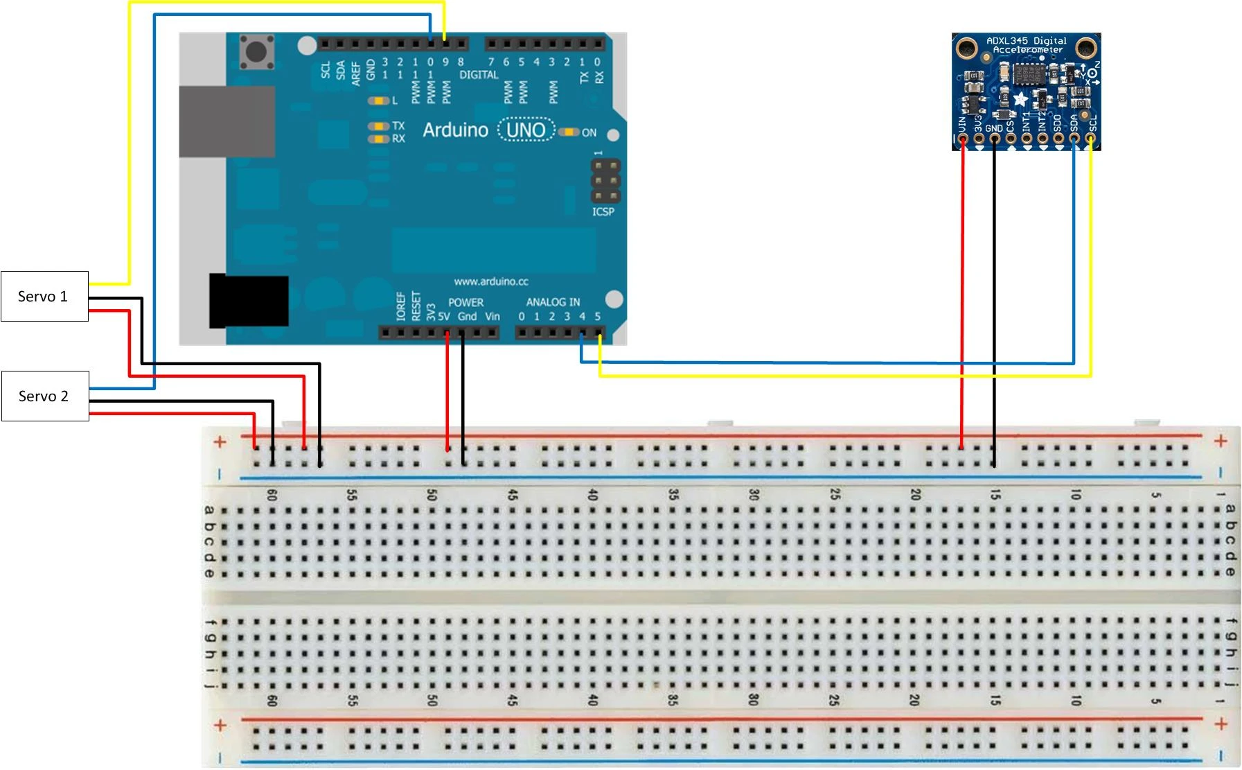
Connect the accelerometer as follows:
VIN --> 5V on breadboard 5V rail
GND --> Ground on breadboard GND rail
SDA --> Analog A4 on Arduino
SCL --> Analog A5 on Arduino
Connect the servos as follows:
Servo 1
Brown Wire --> Ground on breadboard GND rail
Red Wire --> 5V on breadboard 5V rail
Brown Wire --> Pin 10 (Used Yellow Wire)
Servo 2
Brown Wire --> Ground on breadboard GND rail
Red Wire --> 5V on breadboard 5V rail
Brown Wire --> Pin 10 (Used Blue Wire)
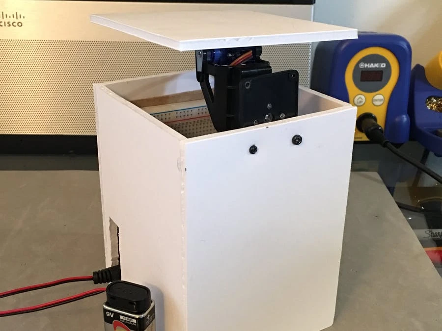
- You can use foam to design the case. You can also use cardboard or 3D print a custom case for that matter.
Working concept
- The working concept for this project is pretty simple and consist of 3 main components: The accelerometer, Arduino, gimbal and servos.
- The accelerometer senses the changes is inclination and then sends that data over to the Arduino board
- The Arduino board upon receiving the angular data from the accelerometer then processes it and then sends the commands to the two servos on the gimbal to rotate accordingly.
- As the servos rotate in the exact opposite direction the floor stays level.
Arduino Code
#include <Servo.h>
#include <Adafruit_ADXL345_U.h>


Servo xServo;
Servo yServo;


int xOffset = -7;
int yOffset = -1;


int sensitivity = 50;


Adafruit_ADXL345_Unified accel = Adafruit_ADXL345_Unified(12345);


void setup() {
      Serial.begin(9600);


      if(!accel.begin())
      {
            Serial.println("No Sensor detected");
      while(1);

      }


      xServo.attach(9);
      yServo.attach(10);


      accel.setRange(ADXL345_RANGE_16_G);
      accel.setDataRate(ADXL345_DATARATE_25_HZ);

}

void loop() {

      sensors_event_t event;
      accel.getEvent(&event);


      int x = event.acceleration.x;
      int y = event.acceleration.y;


      int x1 = map(x, -10, 10, 130, 50);
      int y1 = map(y, -10, 10, 50, 130);


      Serial.print("X: "); Serial.print(x);
      Serial.print("\tY: "); Serial.print(y);
      Serial.print("\tX1: "); Serial.print(x1);
      Serial.print("\tY1: "); Serial.println(y1);


      xServo.write(x1 + xOffset);
      yServo.write(y1 + yOffset);
      delay(sensitivity);
}
Upload the code to the Arduino board. Assemble the circuit diagram. Your leveler is then ready to go

Hot
-59 %
The Arduino Uno R3 Compatible board is an electronic hardware device used to build and program electronic circuits and projects. The board is based on..
₹528 ₹1,299

The MG90S Metal Gear Micro Servo is a high-performance, precision-engineered servo motor designed for a wide range of applications, from robotics and ..
₹246

This is 40pcs of each (40 M-M, 40 M-F, 40 F-F) jumper cable Dupont wire for Arduino.
Specifications:
This is 40 pcs of each (total 120 pcs)..
₹159

Features:-
Model Number: 9V 6F 22.
Battery Type: Zinc Carbon.
Size: 6F22 006P.
Jacket: Metal.
Single Battery Dimensions (mm):..
₹60

The ADXL335 is low power, a complete 3-axis accelerometer with signal conditioned voltage outputs. The ADXL335 Module is a 3-axis Analog Output Accele..
₹678

-37 %
This is 2 Axis Pan Tilt Brackets For Camera/Sensors for Servo SG90S MG90S which is based on 2 axis pan and tilt mechanism for mounting wireless/ wired..
₹75 ₹119

Leave a Comment