22 Dec

Hello,
In this project-based article, we are going to learn how to make an automatic fan using Arduino.
This fan will turn on/off using motion sensing and will control its speed automatically concerning the temperature change.
Hardware Required
-
Axial Fan
Software Required
-
Most of the time, people leave their fans on while leaving the room as they forget to turn it off. They even set their fan to the highest speed irrespective of the weather outside. All these habits consume and waste more and more power each day.
-
The objective of this project is to create a fan that can turn itself on and off automatically. Also, it can change its speed according to the temperature changes inside a room. All these things will save a lot of electrical power.
LM35 Temperature Sensor
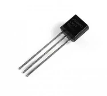
- LM35 is an analog temperature sensor whose output voltage has a linear relationship with the temperature change. The range of this sensor is from -55 degrees Celsius to 150 degrees Celsius.
- The voltage increment for the LM35 sensor is 10mV per degree Centigrade.
- LM35 can be operated on a regulated 5V supply.
PIR Motion Sensor

- The passive infrared sensor is an electronic component that absorbs and measures the infrared radiation emitted by any objects in its vicinity. The term "Passive" is used because this sensor does not emit any infrared light. It just absorbs the radiation emitted by other objects. This infrared radiation is not visible to the human eye as infrared is outside the visible spectrum of the human eye. Every object with a temperature above absolute zero emits infrared radiation. These radiations are measured and converted into electrical signals by the PIR sensor.
- The working of the PIR sensor might seem simple on the surface. But the inside working of the sensor is quite complex.
- This sensor contains two slots. Both slots contain infrared sensing material.
- In equilibrium conditions, both the slots will detect the same amount of radiation. But when an object enters the vicinity of the sensor, the first slot will detect it but the second slot will not. This will create a positive difference between the two slots.
- Similarly, when an object exits the vicinity of the sensor, the second slot will detect it and the first slot will not. This will create a negative difference between the two slots.
- This difference is used to track the motion of an object. The sensor converts all this data into electrical signals.
Circuit Diagram
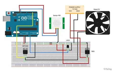
- The circuit diagram for this project is pretty complex as there are so many components.
- Firstly, the PIR sensor signal pin is connected to Arduino pin 12, and the VCC pin of PIR is connected to Arduino pin 13. The ground is connected to GND on a breadboard.
- The axial fan is connected to the Arduino board via a transistor. The transistor pin is connected to the Arduino digital pin 3 and the another pin of the transistor is connected to the axial fan. The third pin is connected to the GND on a breadboard.
- The temperature sensor LM35 has 3 pins: VCC, Signal pin, and GND.
- A voltage regulator is used to convert the 12V to 5V for all the sensors and Arduino.
Working Concept of the Automatic Fan
- The working concept of the automatic fan consists of three things: sensing, sending the signals, and actuation.
- Two different processes are happening at the same time so let us understand both of them separately.
- Firstly, the PIR sensor senses if a person is entering the room. If yes, then it sends the signal to Arduino Board which turns the fan ON, and similarly if the person leaves then it will turn the fan OFF.
- The temperature sensor senses the changes in the temperature of the room. If the temperature goes up, it sends the signal to Arduino which then sends the signal to increase the speed of the fan. Similarly,, if the temperature of the room decreases, the sensor sends the data to Arduino. Arduino then sends the signal to decrease the speed of the fan.
- This completes the working concept of the Automatic fan.
Arduino Code
- Upload the code. Perform the circuit diagram.
Now your Automatic fan is ready for use.

Hot
-59 %
The Arduino Uno R3 Compatible board is an electronic hardware device used to build and program electronic circuits and projects. The board is based on..
₹528 ₹1,299

-18 %
Description:
Tie-point 840
Solderless breadboard (GL-12)
Wire size: Suitable for 29-20 AWG wires
Size: About 16.5*5.6*1cm
Packag..
₹64 ₹78

-50 %
100 ohm Carbon Film Resistors are typical axial-lead resistors, which have much better temperature stability and provide lower noise, and are generall..
₹1 ₹2

-45 %
7805 is a voltage regulator integrated circuit. It is a member of 78xx series of fixed linear voltage regulator ICs. The voltage source in a circuit m..
₹11 ₹20

-28 %
The HC-SR501 PIR Motion Detector Sensor Module is a pyroelectric device that detects motion by measuring changes in the infrared levels emitted by sur..
₹64 ₹89

BC547 is an NPN Transistor. It has a gain value of 110 and a collector current of 100mA.
Package Includes:
1 x BC547 NPN Transistor...
₹6

-0 %
Out Of Stock
LM35 is an integrated analog temperature sensor whose electrical output is proportional to Degree Centigrade. LM35 Sensor does not require any externa..
₹77 ₹77

Leave a Comment