31 Dec

Hello,
In this tutorial based article, we are going to learn how to build an Air quality monitor using Arduino.
Hardware Required
Software Required
- Nowadays, the level of air pollution is increasing exponentially due to rapid increase in number of industries, factories and vehicles. The objective of this project is to design a system which can detect the quality of air in surroundings. This system can further warn the user when the air quality goes below certain level. This system can sense gases like NH3, benzene, smoke, alcohol, Co2 among some other gases.
- These gases are generally harmful for human health. So this project can be perfect for home or even a small office.
MQ-135 Air quality sensor
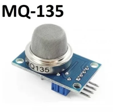
- Like other sensors in the MQ series, the MQ-135 also detects various gases in the atmosphere. Some of them are ammonia, benzene, Sulphur, carbon dioxide etc. which are harmful to humans.
- This sensor also contains 4 pins: two for the power supply and one digital output and one analog output.
- When the levels of these harmful gases go beyond a certain threshold, the output on the digital pin goes HIGH. This threshold can be set using the 10k Potentiometer on the back of the board. The analog output pin gives out an analog voltage which can be used to measure the intensity of these harmful gases.
- This sensor operates on 5V.
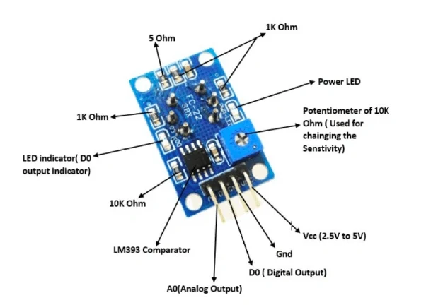
Technical Specifications
- Operating Voltage: 2.5V to 5V.
- Power consumed: 150 mA.
- Operating Voltage: 5V.
- Digital Output: 0V to 5V.
- Analog Output: 0-5V.
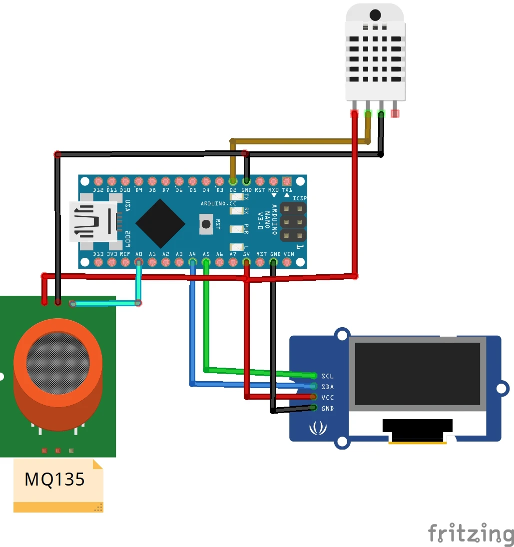
Circuit Diagram
|
Pins on DHT11 Sensor |
Pins on Arduino Nano |
|
VCC |
5V |
|
GND |
GND |
|
Signal Pin |
D2 |
|
Pins on MQ-135 |
Pins on Arduino Nano |
|
VCC |
5V |
|
GND |
GND |
|
A0 |
A0 |
|
Pins on OLED Display |
Pins on Arduino Uno |
|
VCC |
5V |
|
GND |
GND |
|
SDA |
A4 |
|
SCL |
A5 |
Working Concept
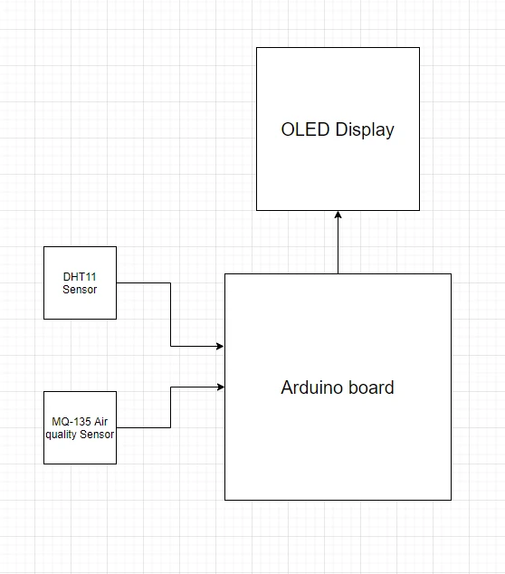
- When we start supplying power to the Arduino board, the MQ-135 sensor starts looking for gases like Ammonia, Benzene, Sulphur, Carbon dioxide etc. And it starts giving the output voltage according to the intensity of the gas present in the air. The output voltage will be converted into parts per million (PPM) by the Arduino board.
- Simultaneously the DHT11 sensor will start taking on temperature and relative humidity values and start sending them to the Arduino board.
- We have divided both of these into two different functions in the Arduino IDE code.
- The DHT11 functions are inside the SendSensor() function and the MQ-135 functions are inside the AirSensor() function.
- Now inside the void loop section, we can just run both these functions one after the other.
- After the processing of the data from both the sensors, the Arduino board displays the final results on the OLED display.
- This cycle is again repeated to get new data.
- You can use any kind of case to enclose this project. We used a 3D printed case for this purpose.
Arduino Code
- Firstly, install the Adafruit_SSD1306.h, Adafruit_GFX.h and the DHT.h libraries inside the Arduino IDE. You can find all of them inside the manage libraries section.
- Upload the code to the Arduino board. Perform the circuit diagram.
Now your Air Quality system is ready for use.

Hot
-59 %
The Arduino Uno R3 Compatible board is an electronic hardware device used to build and program electronic circuits and projects. The board is based on..
₹528 ₹1,299

This is 40pcs of each (40 M-M, 40 M-F, 40 F-F) jumper cable Dupont wire for Arduino.
Specifications:
This is 40 pcs of each (total 120 pcs)..
₹159

-26 %
The MQ 135 Air Quality Detector Sensor Module For Arduino has lower conductivity in clean air. When the target combustible gas exists, the conductivit..
₹103 ₹140

-63 %
This DHT11 Temperature and Humidity Sensor features a temperature & humidity sensor complex with a calibrated digital signal output. By using the excl..
₹38 ₹103

Leave a Comment