04 Feb

Hello,
In this tutorial, we are going to learn about the waterproof ultrasonic sensor JSN-SR04T and its interfacing with Arduino.
Hardware Required
Software Required
- Every one of us who has worked on robotics projects knows about the HC-SR04 Ultrasonic sensor. It is cheap and provides great performance and is small and light in size. It is mainly used in obstacle avoiding and intruder detection robots. But it has its limitations like every other sensor. It can only be used indoors and high winds and dirt will disrupt the readings of the sensor. And it is not waterproof.
- There are ultrasonic sensors available which can withstand much harsher conditions like water, dirt, winds etc. Even though they are more expensive than the HC-SR04, they are not so expensive. One such sensor is the Waterproof Ultrasonic sensor JSN-SR04T. These sensors basically contain a transducer.
Transducers
- A transducer is an electronic component which converts mechanical vibrations into electrical energy and electrical energy into mechanical vibrations. The most common examples of transducers is microphone and speaker.
- Ultrasonic sensors usually have a transducer embedded in them which can work with ultrasonic frequencies. Sensor like HC-SR04 employ two different transducers for transmitting and emitting. Other sensors like JSN-SR04T have only one transducer which can either be used as a transmitter or a receiver at a time.
Working concept of Ultrasonic Sensors
- The working of these sensors is very simple. The ultrasonic sensor emits an ultrasonic sound. This sound travels at the frequency of usually 40 kHz. If there is any object in the vicinity, then the sound gets reflected back. And this reflected sound is sensed by the receiver. To calculate the distance, the time delay between emitting and receiving the sound is calculated first. Then this time lag is used to calculate the distance.
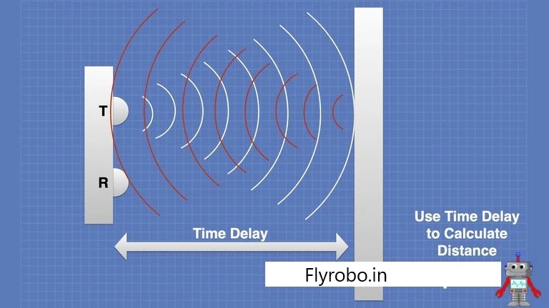
- To calculate the distance, first we must divide the time delay by half (back and forth). Now we need to multiply this time-taken with the speed of sound, which is 343 meters per second in air at normal conditions. This will give us the distance between the sound emitted and the sound reflected. We also need to understand that the speed of the sound is different in different mediums and so one needs to consider it before calculating the distance.
JSN-SR04T
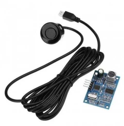
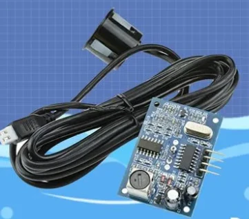
- The sensor JSN-SR04T is a peculiar sensor when it comes to aesthetics. It comes with two parts: one printed circuit board and a transmitter/receiver module which has a 2 meter long wire which can be connected to the printed circuit board.
- The sensor JSN-SR04T can be run in six different modes.
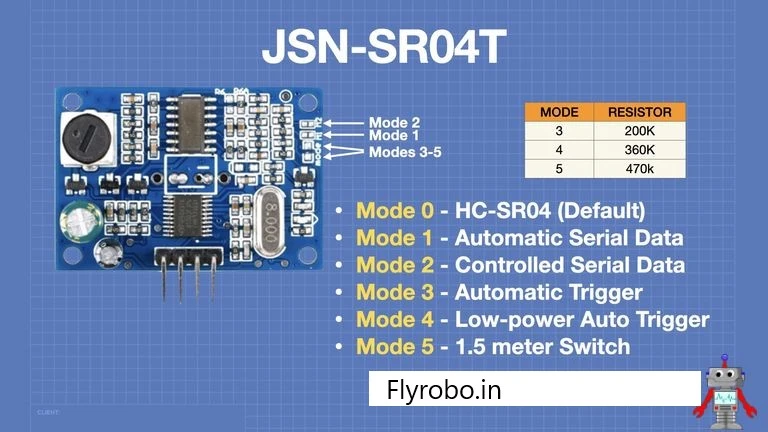
- Mode 0 is the default mode for the sensor
- Modes 1 and 2 can be selected by bridging the traces on the PCB.
- Modes 3, 4 and 5 can be selected by placing a resistor across the traces on the PCB accordingly.
Mode 0: HC-SR04 Emulation
- This is the default mode for this sensor. In this mode, the sensor acts as a mirror image of the Ultrasonic Sensor HC-SR04.
Mode 1: Serial Data
- When the sensor is in mode 1, it will start calculating the distance by itself. And it will then send this data to the microcontroller at the pre-set baud rate. This mode is set by placing a jumper on the M1 points.
- This data is sent in the format of 4 bytes.
- Byte 0 is the first byte. This byte always contains a hexadecimal value. This indicates the start of the block of data which is being sent.
- Byte 1 is the second byte. It contains the high-end of the 16-bit data. This contains the value of distance being sent in millimeters.
- Byte 2 is the third byte. It contains the low-end of the 16-bit data.
- Byte 3 is the fourth byte. It is called the checksum byte and it contains the addition of the first three bytes. This is used to validate the data being sent. The checksum value is checked on the receiving end. It the value differs, then the data is regarded as corrupt.
Mode 2: UART Controlled Output
- Mode 1 sends out Serial data. But with mode 2, it will request the data. This is done by sending the hexadecimal value 55 to the RX pin of the sensor.
- After the request is made, the sensor will measure out the distance and then send it.
- To enter mode 2, you must put a jumper on the M2 points.
Mode 3: Automatic PWM
- In this mode, the sensor again acts like an HC-SR04 but this time it does not require a trigger signal. This time the sensor provides its own trigger signal every 200ms. You can read the said data on the echo pin.
- This mode is activated by placing a 200k resistor across the mode pins.
Mode 4: Low-Power HC-SR04
- This mode is very similar to the mode 3. The sensor just uses far less current in this mode. This is done by disabling the internal timer of the sensor. This decreases the current usage to less than 70ua.
- This mode is activated by pulling a 360k resistor across the mode pin.
Mode 5: Switched Output
- This mode turns the sensor into a switch. The distance is preset at 1.5 meters. So whenever an object comes within 1.5 meters of the sensor, the output will go HIGH. No data about the distance will be sent by the sensor.
- This mode acts as a perfect candidate for intruder detection alarms.
- This mode can be activated by pulling a 470k resistor between the mode pins.
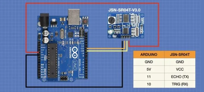
Interfacing with Arduino
Arduino Code
- Upload this code for mode 0 testing.
#define TRIGPIN 11
#define ECHOPIN 10

float duration, distance;

void setup() {

  Serial.begin(115200);

  pinMode(ECHOPIN, INPUT);
  pinMode(TRIGPIN, OUTPUT);
}

void loop() {

  digitalWrite(TRIGPIN, LOW);
  delayMicroseconds(2);

  digitalWrite(TRIGPIN, HIGH);
  delayMicroseconds(20);

  digitalWrite(TRIGPIN, LOW);

  duration = pulseIn(ECHOPIN, HIGH);

  distance = (duration / 2) * 0.343;

  Serial.print("distance: ");
  Serial.print(distance);
  Serial.println(" mm");

  delay(100);
}
Upload this code for mode 1 testing.
#INCLUDEINT PINRX = 10; INT PINTX = 11; UNSIGNED CHAR DATA_BUFFER[4] = {0}; INT DISTANCE = 0; UNSIGNED CHAR CS; T SOFTWARESERIAL MYSERIAL(PINRX, PINTX); VOID SETUP() { SERIAL.BEGIN(115200); MYSERIAL.BEGIN(9600); } VOID LOOP() { IF (MYSERIAL.AVAILABLE() > 0) { DELAY(4); IF (MYSERIAL.READ() == 0XFF) { DATA_BUFFER[0] = 0XFF; FOR (INT I = 1; I < 4; I++) { DATA_BUFFER[I] = MYSERIAL.READ(); } CS = DATA_BUFFER[0] + DATA_BUFFER[1] + DATA_BUFFER[2]; IF (DATA_BUFFER[3] == CS) { DISTANCE = (DATA_BUFFER[1] << 8) + DATA_BUFFER[2]; SERIAL.PRINT("DISTANCE: "); SERIAL.PRINT(DISTANCE); SERIAL.PRINTLN(" MM"); } } } }
- I hope you learned something about waterproof ultrasonic sensors in this article and I hope you liked it.

Hot
-59 %
The Arduino Uno R3 Compatible board is an electronic hardware device used to build and program electronic circuits and projects. The board is based on..
₹528 ₹1,299

This is 40pcs of each (40 M-M, 40 M-F, 40 F-F) jumper cable Dupont wire for Arduino.
Specifications:
This is 40 pcs of each (total 120 pcs)..
₹159

-66 %
This Ultrasonic Distance Sensor is an industrial-grade sensor to measure distance. Interfacing with it is the same as another cheap ultrasonic sensor,..
₹278 ₹829

Leave a Comment