26 Jan

Hello,
In this article, we are going to learn more about vibration sensors and interface them with the Arduino board.
Hardware Required
Software Required
Vibration Sensor SW-420
- The SW-420 is a vibration sensor that comprises resistors, capacitors, potentiometers, LM393 IC, power, and status LED in an integrated circuit. It is useful to detect a variety of shocks. So it has various applications like theft alarms, earthquake alarms, etc.
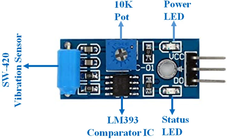
- The LM393 IC is used as a voltage comparator. There are three pins to this sensor. The second pin is connected to the preset timer and the third pin is connected to the main vibration sensor. The comparator's main function is to compare the voltage from the vibration sensor to the threshold voltage.
- The preset in this case is a 10K potentiometer. This potentiometer is used to set the threshold of the digital output.
- The vibration sensor measures the vibration in the vicinity and then it gives a voltage output concerning the intensity of the vibration.
- The above picture shows the pinout of the vibration sensor.
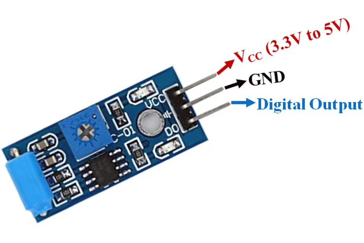
- It contains three pins one VCC, one GND, and one for digital output.
Specifications
- Operating Voltage: 3.3V / 5V.
- Operating Current: 15mA.
- Interfacing: Digital.
- Weight: 4.3g.
- Threshold: Adjustable.
- Comparator IC: LM393
Interfacing with Arduino
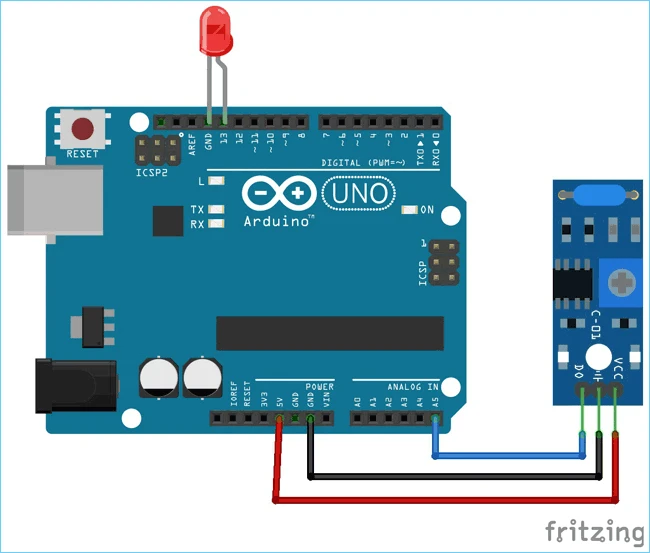
- For interfacing with Arduino, the circuit diagram is pretty simple as it only consists of two components: the SW-420 vibration sensor and the Arduino board.
|
Pins on Arduino Uno |
Pins on SW-420 Sensor |
|
VCC |
5V |
|
GND |
GND |
|
D0 |
A5 |
Working Concept
- The working concept involves two processes: Sensing and processing.
- The vibration sensor senses the intensity of the vibration and outputs a voltage which is then sent to the LM393 comparator IC.
- The comparator compares the voltage to that of the threshold voltage. If the voltage is higher than the threshold, then the LM393 provides the output to be logic HIGH otherwise during normal conditions the output is logic LOW.
- These signals are then sent to the Arduino board. If the board receives the output to be HIGH then it will give the command to light up the LED otherwise it will do nothing.
Arduino Code
#include#include #define ON 1 #define OFF 0 int vibration_Sensor = A5; int LED = 13; int present_condition = 0; int previous_condition = 0; void setup() { pinMode(vibration_Sensor, INPUT); pinMode(LED, OUTPUT); } void led_blink(void); void loop() { previous_condition = present_condition; present_condition = digitalRead(A5); if (previous_condition != present_condition) { led_blink(); } else { digitalWrite(LED, OFF); } } void led_blink(void) { digitalWrite(LED, ON); delay(250); digitalWrite(LED, OFF); delay(250); digitalWrite(LED, ON); delay(250); digitalWrite(LED, OFF); delay(250); }
- Upload the code to the Arduino board.
- I hope you learned something about the vibration sensor and its interfacing with Arduino in this article.

Hot
-59 %
The Arduino Uno R3 Compatible board is an electronic hardware device used to build and program electronic circuits and projects. The board is based on..
₹528 ₹1,299

This is 40pcs of each (40 M-M, 40 M-F, 40 F-F) jumper cable Dupont wire for Arduino.
Specifications:
This is 40 pcs of each (total 120 pcs)..
₹159
")
Features and Specifications :
Product : LED Diod (Light Emitting Diod)
Light Colour : Red
LED Type : 5mm
..
₹5

-49 %
Out Of Stock
SW-420 normally closed a highly sensitive axial vibration sensor switch moisture and dustproof housing. Vibration resistance varies with the intensity..
₹4.56 ₹9

Leave a Comment