
Hello,
In this tutorial-based article, we are going to learn how to make a working traffic light system for a three-way road using Arduino.
Hardware Required
Software Required
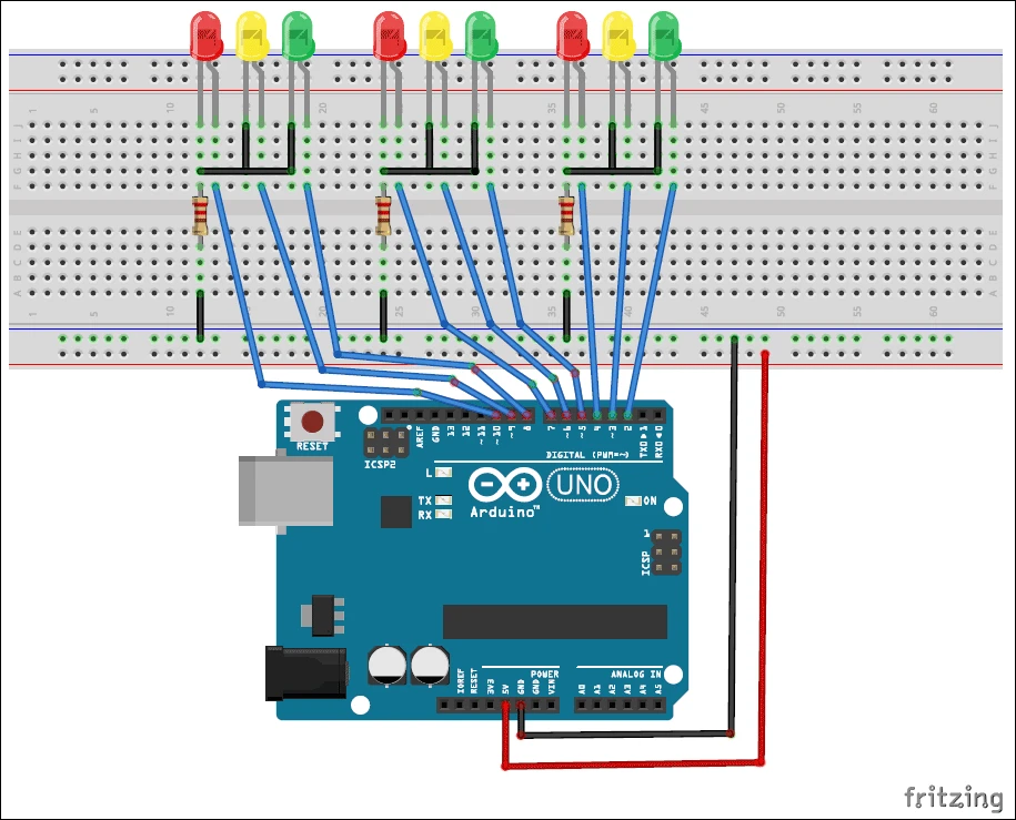
Circuit Diagram
-
Connect the 220-ohm resistor to the negative terminals of the LED.
-
Then connect all the negative terminals to the ground on the breadboard.
-
Connect Arduino pins 2 to 10 to the positive terminals of the LED.
-
Connect the 5V pin on the Arduino to the positive line on the breadboard and GND to the negative terminal of Arduino.
The working concept of the traffic light system
-
The traffic light system is necessary to ensure the proper flow of cars through a city. Without a properly installed traffic light system, every road in the city would have traffic jams. A traffic signal is used to instruct a driver whether to stay put or go ahead.
-
There are three different colors of traffic lights: Red, Yellow, and Green. When the Red light is on the driver is indicated to stay. Yellow light is used as a transitional light between Red and Greenlight. The Greenlight indicates the driver can go ahead.
-
In a three-way traffic light system, at any point in time, two of the lights are red and one is green. During the transition period, two of the lights turn yellow and one stays red. The time set for a light to stay Red is 10 seconds, to stay Yellow is 2 seconds and the time to stay Green is 10 seconds.

Arduino Code
|
-
Upload the code to the Arduino board and the system will start working as soon as it is powered.
-
One of the disadvantages of this system is that it can just be used for demonstration purposes. It is not very practical as any changes to be made in the system have to be made inside the code in IDE. Whereas in real-life traffic light systems, the operator can manually change the timing of the lights.
Now your traffic light system is ready for use!


")

Leave a Comment