-1060x400h.webp "How to build a robotic Arm using Arduino")
Hello,
In this tutorial-based article, we are going to learn how to make a robotic arm with Arduino.
Hardware Required
Software Required
Robotic Arm
- The robotic Arm is one of the most common concepts which is used for project purposes in the mechatronics and robotics industry. Robotic arms have a wide variety of applications. Ranging from being used on assembly lines to packaging lines in manufacturing plants.
- At first, the thought of building a robotic arm might sound complex and gruesome. But after learning the physics behind it and going more in-depth to the topic. You will understand that it is not that hard.
- This robotic arm consists of 4 servo motors. This means that the degree of freedom for this robot is 4.
- Degrees of freedom (DOF) of a body are defined by the number of parameters it takes to define the position of that same body.
Chassis for the Robotic Arm
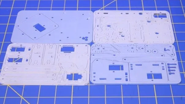
- There are many different chassis for the robotic arm which are available for free on the internet. These chassis can be laser cut on an acrylic sheet, they can also be 3D printed using the .stl files.
- The chassis we used was laser cut from the .dxf file. It can be downloaded here.
- This is what the laser-cut acrylic sheet will look like.
Assembly of the Robotic Arm
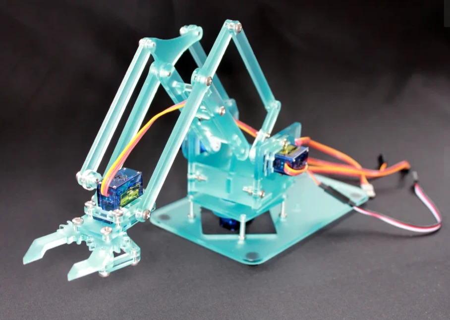
- The Manual for the assembly of the robotic arm can be found here. In this manual, the complete process of how to assemble a robotic arm has been explained with proper pictures and documentation.
- The fully assembled robotic arm is shown in the below picture.
Circuit Diagram
There are quite a few variations for circuit diagrams for this robot depending upon its method of control:
-
We can control the full robotic arm with two joysticks.
-
We can control it with potentiometers.
-
We can control it with a smartphone via Bluetooth.
-
We can control it with programming via the Arduino IDE.
We are going to look at the circuit diagram of every one of them. But we are going to look at the code for the potentiometer model only.
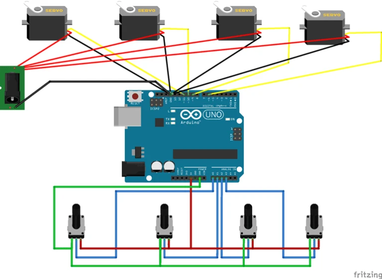
Potentiometer model
- In this model, we are going to use 4 different potentiometers to control 4 different servos. All the positive terminals of the servo are connected directly to the power supply.
|
Pins on Arduino |
Signal pins of Servo |
|
7 |
Base Servo |
|
9 |
Shoulder servo |
|
10 |
Elbow Servo |
|
11 |
Gripper servo |
- The positive pins on all potentiometers are connected to the 5V pin on Arduino and the GND pins are connected to GND on Arduino.
|
Pins on Arduino Uno |
Signal Pins on Potentiometer |
|
A0 |
Base potentiometer |
|
A1 |
Shoulder potentiometer |
|
A2 |
Elbow potentiometer |
|
A3 |
Gripper potentiometer |
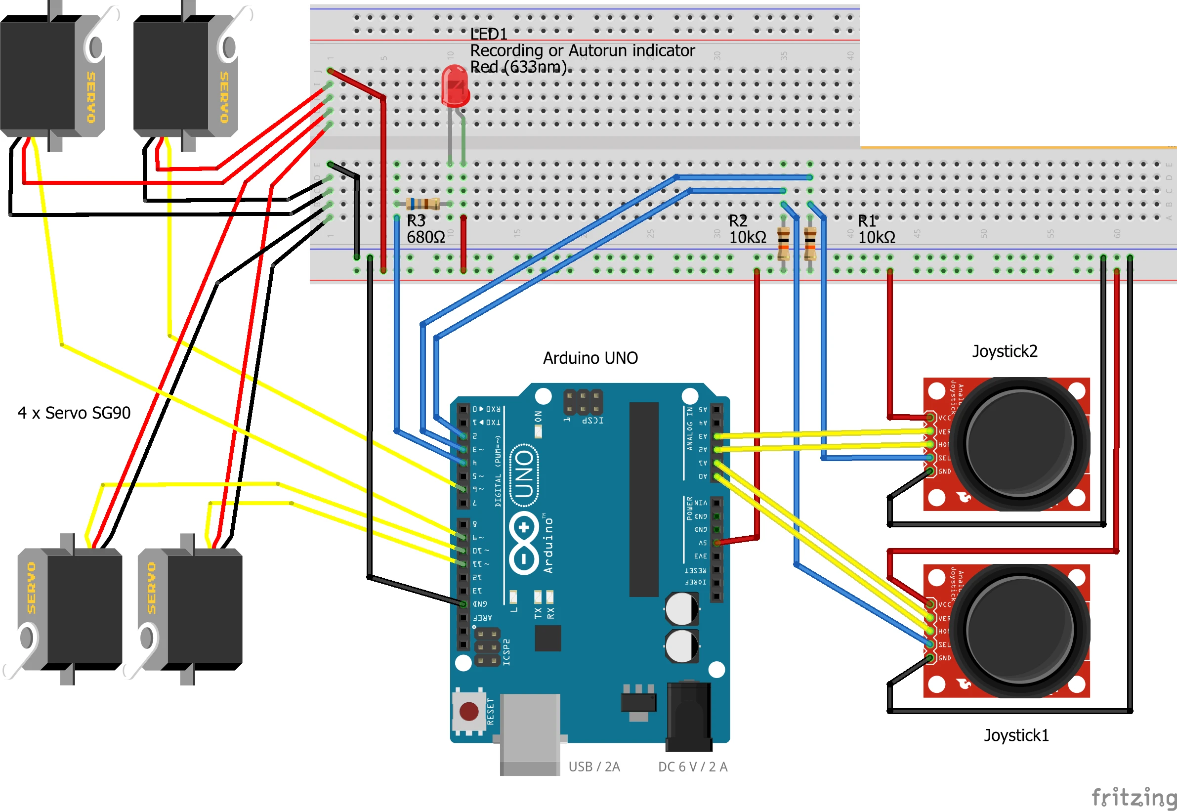
Joystick model
- The joystick model might seem a bit complicated, but it is not. The potentiometers have just been replaced by the joysticks. There are two signal pins in a joystick namely "Vert" for vertical movement and "Horz" for horizontal movement.
- All the positive terminals of servos and the joystick are connected to the 5V pin on Arduino and negative terminals are connected to the GND pin on Arduino.
|
Pins on Joysticks 1 and 2 |
Pins on Arduino Uno |
|
Horz 1 |
A0 |
|
Vert 1 |
A1 |
|
Sel 1 |
Digital Pin 2 |
|
Horz 2 |
A2 |
|
Vert 2 |
A3 |
|
Sel 2 |
Digital Pin 3 |
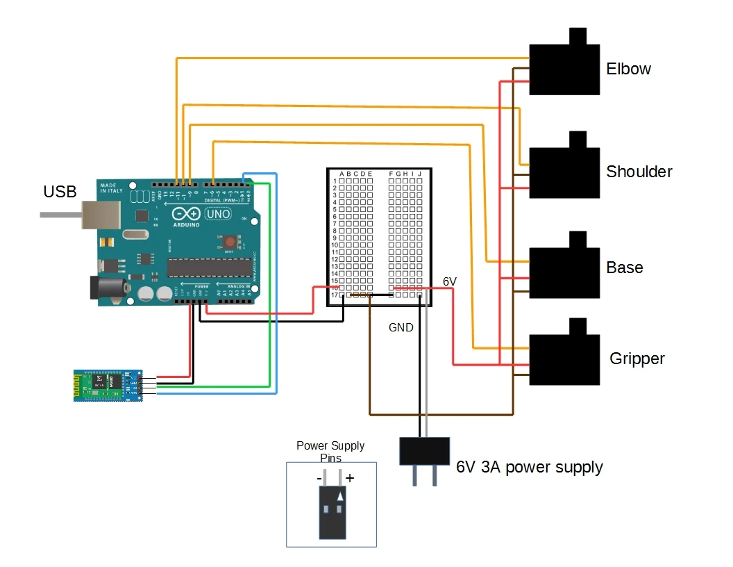
Bluetooth Model
- This model is quite simple as it only contains an HC-05 Bluetooth module. It has 4 pins: VCC, GND, Tx, Rx.
- The negative and positive terminals of the servos are connected to the negative and positive terminals of the external power supply respectively.
|
Pins on Bluetooth |
Pins on Arduino Uno |
|
VCC |
5V |
|
GND |
GND |
|
Tx |
Rx |
|
Rx |
Tx |
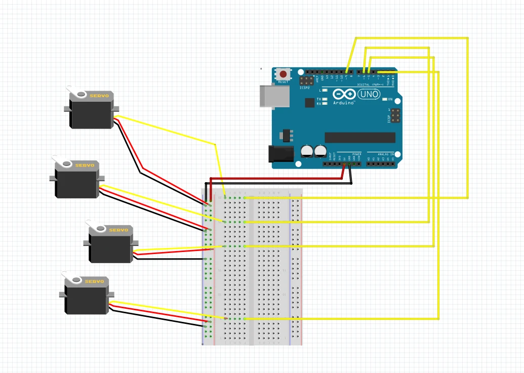
Arduino IDE model
- In this model, the only way to control the movement of servos is through programming in Arduino IDE. So there are no methods of controlling the motors externally.
- This method is not feasible as every time you have to change the movement of the robotic arm, you have to make the necessary changes in the Arduino code.
- The below photo shows the circuit diagram for such a model.
Arduino Code
- In this project, we are going to look at the potentiometer model only. So we are only going to discuss that code.
- Upload the code to the Arduino board. Perform the circuit diagram.
Now your robotic arm is ready for use.


Leave a Comment