07 Feb

0 Comment(s)
4618 View(s)
Hello,
In this article, we are going to understand how RF Receiver and transmitter work.
In this article, we are going to understand how RF Receiver and transmitter work.
In Infrared connection, there is a line of sight required for the data transfer but in Radio frequency communication, no such thing is required. This makes the range of RF communication higher than that of IR communication.
Radio frequency modules operate in somewhere between 30kHz to 300 GHz. In RF communication, the data is sent in the form of changes in amplitude of the carrier wave. This phenomenon is called Amplitude Shift Keying. Any RF communication system consists of two parts: RF transmitter and RF receiver. This Tx/Rx pair operates at the frequency of 433 MHz.
The RF transmitter receives and transmits serial data wirelessly through the RF antenna. The transmission speed is anywhere between 1 - 10 kbps. RF receiver receives the data and is operating the same frequency as the transmitter.
Specifications of RF module
- Communication frequency : 433 MHz
- Receiver operating current 3.5 mA
- Low power consumption
- Operating Voltage of receiver is 5V
- Operating voltage of transmitter is anywhere between 3 to 6V.
- Output power of transmitter is between 4 Dbm to 12 Dbm.
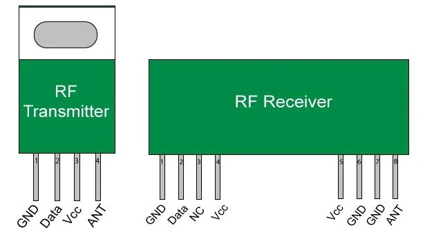
The transmitter has 3 pins: VCC, Din and GND. The Din pin is used for the data transfer. The VCC pin accepts anywhere between 3-12V.
The receiver has 4 pins: VCC, GND, Dout and linear out. The Dout and Linear out pins are shorted together so that they can receive signals from the air.
- The purpose of this tutorial is to show a basic project about how RF communication works. It involves making two different circuits: one receiver and one transmitter circuit.
- The transmitter circuit consists of an RF Transmitter, an Arduino Uno and a temperature sensor.
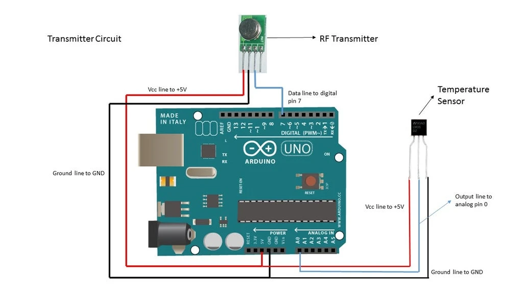
- RF transmitter data line is connected to digital pin 7. VCC and GND are connected to 5V and GND pins on Arduino board respectively.
- The output line of the LM35 temperature sensor module is connected to the A0 pin in Arduino. The VCC and GND are connected to 5V and GND on Arduino board respectively.
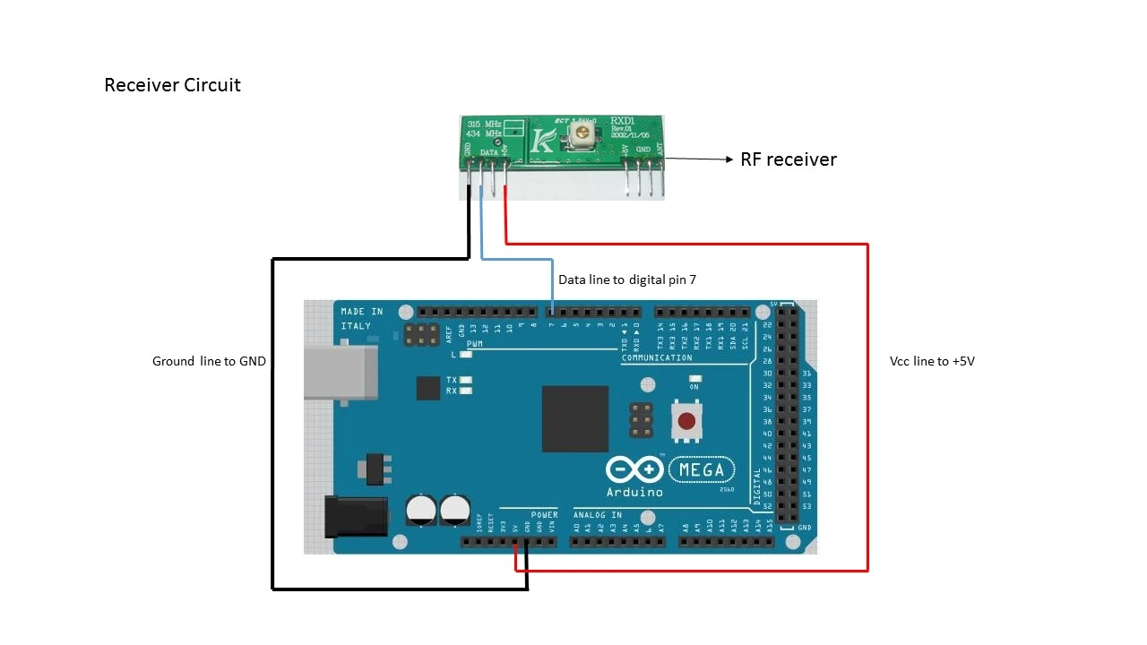
- The receiver circuit consists of two components: And Arduino Mega and an RF receiver.
- The data pin of RF receiver is connected to digital pin 7. The VCC and GND pins are connected to 5V and GND pins respectively.
Arduino Code
- Firstly, you need to install VirtualWire library in your Arduino IDE. You can download it from here.
- Then upload the below mentioned code to the Arduino board
- Transmitter code
#includeint temp; int sensePin = 0; char data[5]; void setup() { Serial.begin(9600); vw_set_ptt_inverted(true); vw_setup(2000); vw_set_tx_pin(7); analogReference(DEFAULT); pinMode(0,INPUT); } void loop() { temp = analogRead(sensePin); changeC(temp,data); vw_send((uint8_t*)data,2); delay(3000); } void changeC(int num,char *data) { int k = num,i = 0,j; while (k > 0) { k/=10; i++; } int l = i; for (i = 0,j = l-1; i < l; i++,j--) { data[j] = char(num%10+48); num/=10; } }
Receiver code
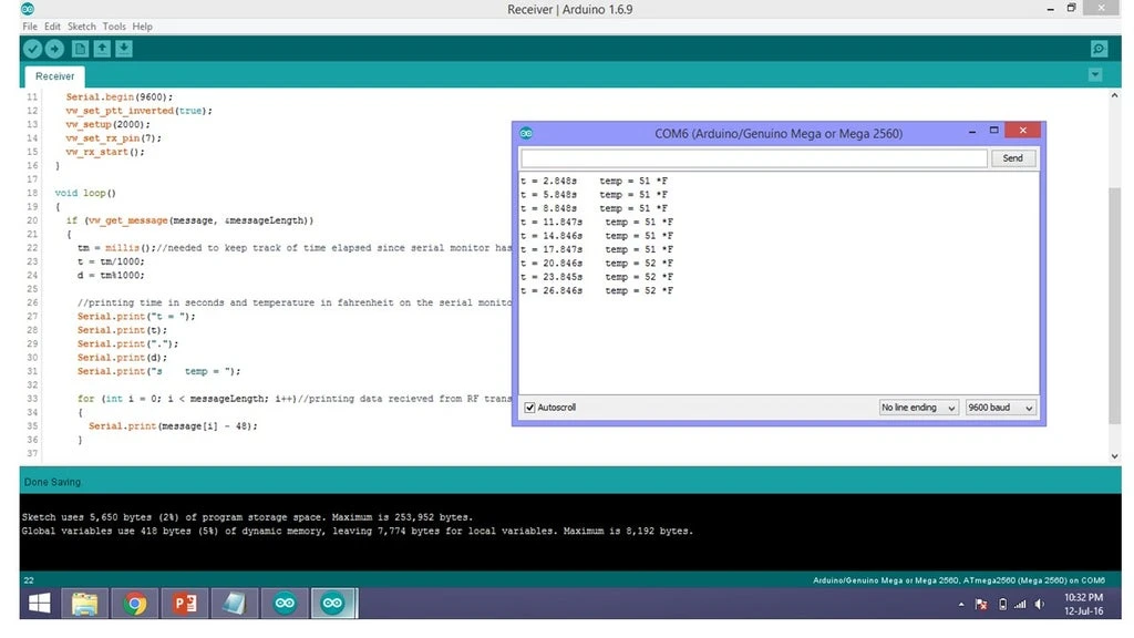
#include
#include

long tm, t, d;

byte message[VW_MAX_MESSAGE_LEN];
byte messageLength = VW_MAX_MESSAGE_LEN;

void setup()
{
  Serial.begin(9600);
  vw_set_ptt_inverted(true);
  vw_setup(2000);
  vw_set_rx_pin(7);
  vw_rx_start();
}

void loop()
{
  if (vw_get_message(message, &messageLength))
  {
    tm = millis();
    t = tm / 1000;
    d = tm % 1000;


    Serial.print("t = ");
    Serial.print(t);
    Serial.print(".");
    Serial.print(d);
    Serial.print("s    temp = ");

    for (int i = 0; i < messageLength; i++)
    {
      Serial.print(message[i] - 48);
    }

    Serial.println(" *F");
  }
}
- Upload these codes to their respective boards.
- Now you can see the data on Serial monitor of receiver code.

Leave a Comment