06 Feb

Hello,
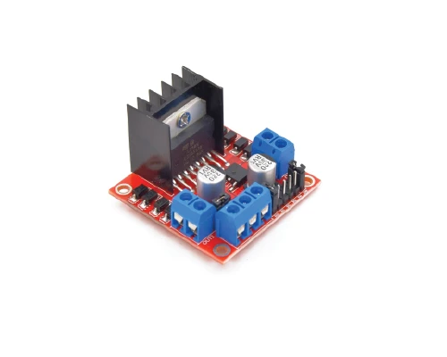
In this article, we are going to learn in-depth about the L298N motor driver.
In this article, we are going to learn in-depth about the L298N motor driver.
Almost every robot contains a DC motor. And DC motors need a motor driver for control purposes. L298N is a motor driver which can control the speed and direction of up to two DC motors. This motor driver is one of the cheapest and the easiest way to control DC motors. One more advantage is that it can control a stepper motor as well.
- There are two working concepts behind controlling the speed and the direction of a DC motor. Pulse width modulation is used to control the speed of the motor. H-bridge connections are used to change the direction of the motor.
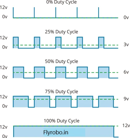
- The speed of the DC motor depends mainly on the input voltage it receives. So by varying the input voltage, we can vary the speed of a DC motor. This process is called Pulse Width Modulation (PWM).
- In pulse width modulation, the voltage is varied by sending a series of ON-OFF pulses.
- The average voltage during the PWM depends on the duty cycle. The higher the duty cycle is, the higher the average voltage is and the lower the duty cycle is, the lower the average voltage. The relation between duty cycle and average voltage is shown in the below picture.
- The direction of a DC motor is dependent on the polarities of the input voltage. If we change the polarities of the input voltage, then the direction of the motors will also be changed. The most common technique for changing the polarities of the motor is called an H-bridge circuit.
- An H-bridge contains 4 switches and the motor in between looking like the alphabet H. Any 2 switches are closed at the same time. The combination of these two switches helps in changing the direction of rotation of the motor. The below animation will illustrate exactly how an H-bridge connection works.
.gif)
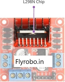
- The main central processing unit of the L298N motor driver is the the L298N chip which comes with a big, black heat sink. The L298N IC is a dual channel H-bridge motor which can run two DC motors simultaneously. This makes the L298N motor driver ideal for two and four wheeled projects.
- The power supply pins include 3-pins screw terminal which are used to supply the power to both the motor and logic circuitry. The pins include motor power supply (Vs), ground and 5V Logic power supply (Vss).
- This motor driver also includes an on-board voltage regulator 78M05 5V. You will have to use a jumper to enable it.

- There is a voltage drop of about 2V due to the H-bridge transistors. So if we want to run a 12V motor, approximately we will have to supply around 14V to the power supply pin.
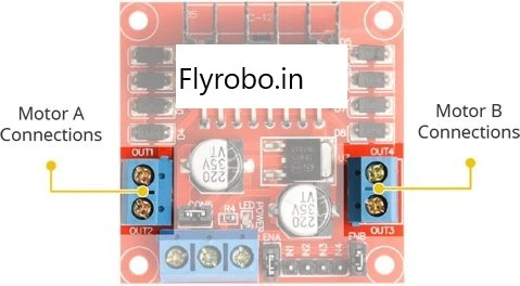
- The motor driver output pins for both the motors are provided on the boundary of the motor driver. There are 3.5mm screw terminals provided on both the sides to connect the DC motors.
- These motors can be anywhere from 5-35V. Each terminal can supply upto 2A to the DC motor. However, this depends on the main power supply.
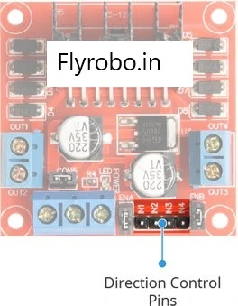
- Using the directional control pins we can easily control the direction of rotation of the motors. There are 4 pins which control the 4 switches inside the H-bridge inside the L298N IC. The IN1 and IN2 pins are for motor A whereas the IN3 and IN4 pins are for motor B.
- Below given is the truth table for the direction of rotation.
- There are two other pins located on either side of the directional control pins. These are the speed control pins ENA and ENB. These pins are generally shorted as the speed of the motor is constant in most of the projects.
- Pulling these pins HIGH will start the motors and pulling these pins LOW will stop the motors. Further we can control the duty cycle and vary the speed of the motors.
Pinout of L298N motor driver
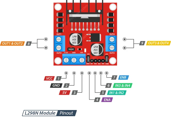
- VCC pin supplies the power to the motors. It can be anywhere from 5-35V
- GND pin is the common ground pin.
- 5V pin supplies the power to the logic circuitry inside the L298N IC.
- ENA pin is the enable pin for motor A. Pulling this pin HIGH will make the motor rotate. It can also be used to control the speed of the motors.
- IN1 and IN2 pins are used to control the spinning direction of the motor A.
- IN3 and IN4 pins are used to control the spinning direction of the motor B.
- ENB pin is the enable pin for motor B. Pulling this pin HIGH will make the motor B rotate.
- OUT1 and OUT2 pins are connected to the motor A.
- OUT3 and OUT4 pins are connected to the motor B.
Interfacing with Arduino
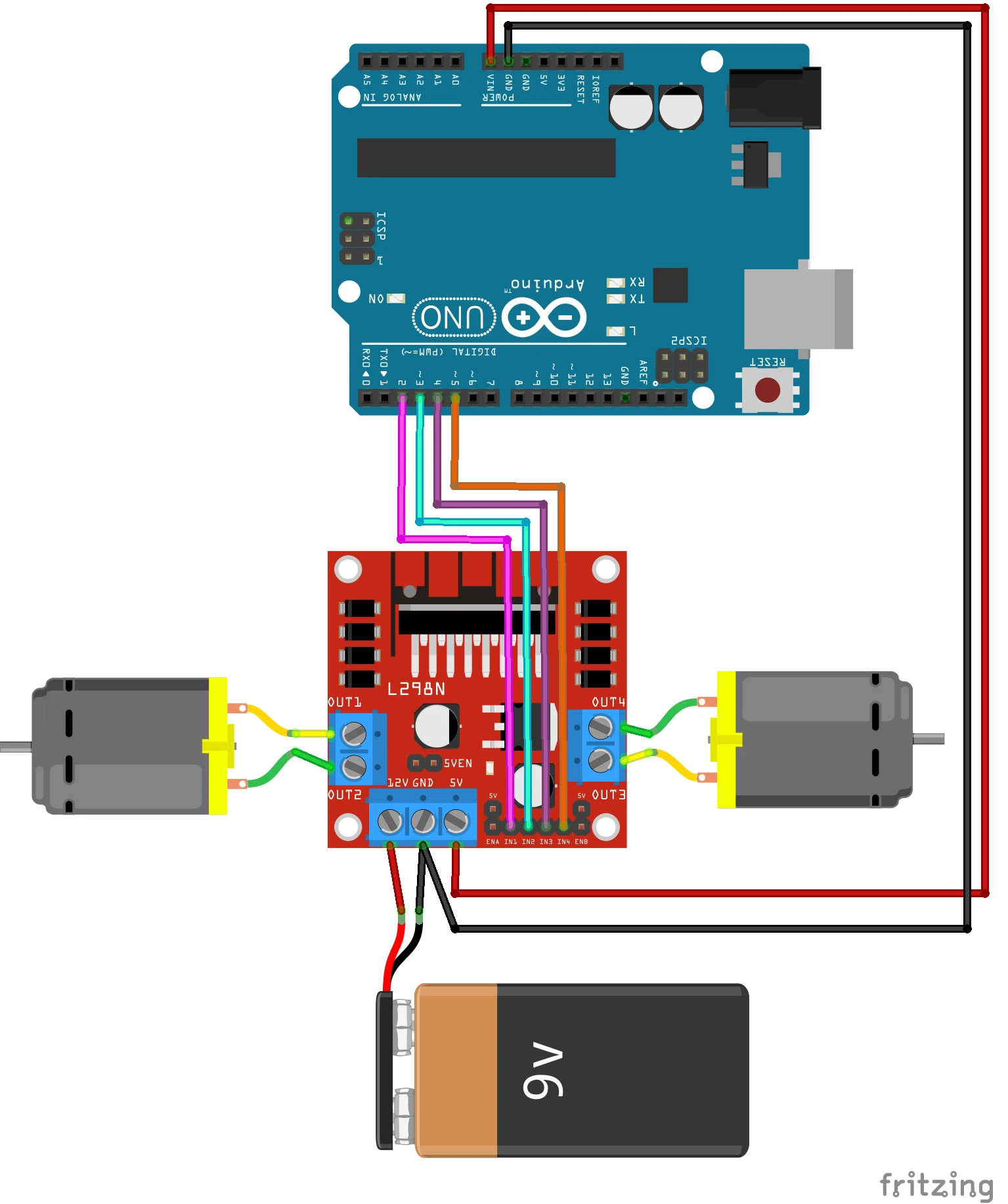
Arduino Code
int motor1pin1 = 2;
int motor1pin2 = 3;

int motor2pin1 = 4;
int motor2pin2 = 5;

void setup() {
  pinMode(motor1pin1, OUTPUT);
  pinMode(motor1pin2, OUTPUT);
  pinMode(motor2pin1, OUTPUT);
  pinMode(motor2pin2, OUTPUT);
}

void loop() {
  digitalWrite(motor1pin1, HIGH);
  digitalWrite(motor1pin2, LOW);

  digitalWrite(motor2pin1, HIGH);
  digitalWrite(motor2pin2, LOW);
  delay(1000);

  digitalWrite(motor1pin1, LOW);
  digitalWrite(motor1pin2, HIGH);

  digitalWrite(motor2pin1, LOW);
  digitalWrite(motor2pin2, HIGH);
  delay(1000);
}

Leave a Comment