
Hello,
In this tutorial, we are going to discuss in detail the NodeMCU ESP8266 board.
Introduction
-
If you have completed various Arduino projects and are familiar with Arduino, using NodeMCU instead of Arduino Uno is the logical next step if you’re looking for a more compact module that encompasses Wi-Fi. NodeMCU is predicated on the Esperessif ESP8266-12E Wi-Fi System-On-Chip. It is based on Lua-based firmware and is open-source.
-
It’s perfect for IoT projects, especially other Wireless connectivity projects as Arduino does not work wirelessly. We either need to connect it to a Bluetooth or nRF module This chip has a great deal in common with the Arduino – they’re both microcontroller-equipped prototyping boards that can be programmed using the Arduino IDE. The ESP8266 is more updated and younger than Arduino, and therefore the ESP has stronger specifications than Arduino.
![]()
Specifications & Construction
- Operating Voltage: 2.5 to 3.3V
- Operating current: 800 mA
- 3.3V 600mA on-board voltage regulation
- ESP8266 comes up with 2 switches one is reset and another one is flash button, Reset button is used to reset NodeMCU and flash button is used to download and is used while upgrading the firmware. The board has build in LED indicator which is connected to D0 pin.
- The NodeMCU board also contains a CP2102 USB to UART module to convert the data from USB to serial so that it can be controlled and programmed via computer.
- The esp8266 has 4 power pins: One VIN pin for input power supply and three 3.3V pins for output power supply. Even if 5V regulated supply is given through VIN, the voltage regulator will decrease it to 3.3v during output.
- The esp8266 has 3 GND pins which indicate ground supply. Generally, the negative terminals are connected to these pins.
- Esp8266 board also has I2C pins which can be used both as I2C master and I2C Slave. These pins are used to connect various I2C sensors and peripherals in your project. I2C interface functionality can be controlled via programming, and the clock frequency is 100 kHz at a maximum.
- Esp8266 NodeMCU has 17 GPIO pins which can be assigned to various functions such as UART, PWM, I2C,IR and Button via programming. When configured as an input pin, the GPIO pins can also be set to edge-trigger or level-trigger to generate CPU interrupts.
- ESP8266 NodeMCU has 2 UART interfaces, i.e. UART0 and UART1, which offer asynchronous communication, and may communicate at up to 4.5 Mbps. TXD0, RXD0, RST0 & CTS0 pins can be used for communication. It supports fluid control. However, TXD1 pin features only data transmit signal so, it's usually used for printing log.
- ESP8266 has two SPI in slave and master modes. These SPIs also support the following general features: 4 timing modes of the SPI format transfer. Up to 64-byte FIFO buffer.
- Esp8266 has a secure digital I/O interface which is used directly control the SD cards.
- Esp8266 has 4 channels of Pulse width modulation (PWM). The output can be controlled via programming and is frequently used for driving motors and LEDs. The frequency ranges from 100Hz to 1KHz.
- There are three control pins on the esp8266: The enable pin (EN), the reset pin (RST) and the wake pin.
- The esp8266 chip works when the enable pin is high. When the enable pin is low, the chip works on minimum power.
- The reset pin is used to reset the esp8266 chip.
- The wake pin is used to wake up the chip from deep sleep mode.
How to upload programs on to ESP8266 from Arduino IDE
- Firstly, you need to download the Arduino IDE. If you already have installed then it is ok. Otherwise you can download the Arduino IDE from here.
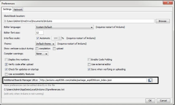
- Now open the IDE and follow this path. File -> preferences -> Additional board manager URL.
- Now paste the URL in the dialog box : http://arduino.esp8266.com/stable/package_esp8266com_index.json
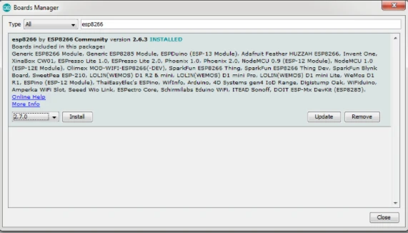
- Now follow this path. Tools -> Board -> Boards Manager
- Now in the search bar, type esp. There will be esp8266 listed in the boards below. Download and install the latest version for you Arduino IDE.
- After the installation is complete, open Tools -> Board-> Select the NodeMCU 1.0
- Now your board is installed and selected. There are various settings which can be changed right from the IDE now.
- You can now upload the code to NodeMCU right from the Arduino IDE.
That is it. Hope you learn something from this blog. And I hope you like it. If you have any doubts you can ask them in the comments section below. Thank you!


Leave a Comment