
Hello,
In this tutorial, we are going to learn how the nRF24L01 modules work.
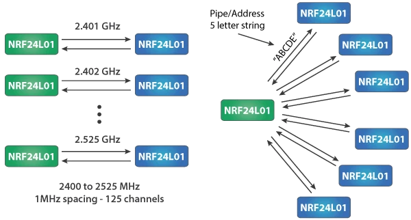
The nRF transceiver module is a 2.4 GHz band module and it operates on the baud rates between 250 Kbps and 2 Mbps. In an open space, the lower baud rates can give out a range upto 100 meters. The nRF module offers a 125 different channels which means there are 125 different modem setups possible. And a single channel can hold upto six addresses. This means that each nRF module can connected and send data to another six nRF modules on a single channel.
The operating current of the nRF module is around 12 mA when transmitting which is lower than a working LED. The operating voltage of the nRF module is 1.9 to 3.6 volts. But the pins can tolerate 5 volts so it can easily be used with Arduino pins.
![]()
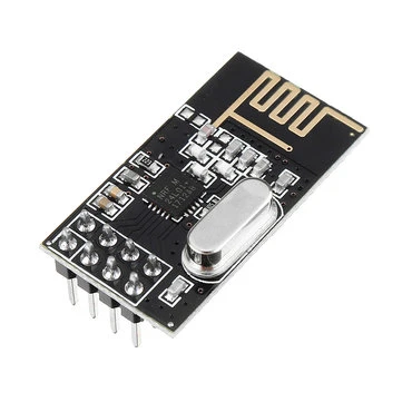
The nRF module uses SPI communication protocol for interfacing with Arduino. So there are three SPI pins: MISO, MOSI and SCK situated on the nRF module. The detailed specifications of the nRF module are listed below.
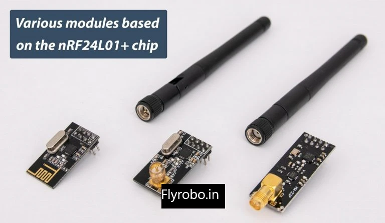
There are several different variations of nRF24L01 module. The most commonly used module is the on-board antenna version. This makes the module more compact, but also decreases the range of transmission to about 100 meters. This kind of version is good for indoor communications.
In the second version, an SMA connector is used instead of the on-board antenna. The SMA can also attach a duck antenna for better transmission.
The third variation includes only a duck antenna instead of the SMA connector. It contains an RFX2401C chip which includes Power Amplifier (PA) and Low-Noise Amplifier (LNA). Both of these amplify the signal and boost the transmission range to upto 1000 meters in clear line of sight.
The Power amplifier only boost the power of the signal being transmitted. Whereas the Low-noise amplifier takes very low and uncertain signals and amplifies them to a more perceptive stage.
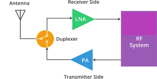
The low-noise amplifier on the receiver side and the power amplifier on the transmitter side make up for the perfect combination to increase the quality and range of the transmission. They are connected by a duplexer which separates the PA and the LNA so that the high powered PA does not damage the LNA.
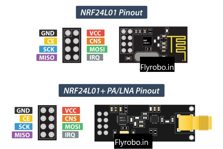
- GND is the ground pin.
- VCC is the power supply pin. You can supply anywhere between 1.9-3.9 volts. You can use the 3.3V Arduino pin for this purpose but not the 5V pin. That will destroy the nRF module.
- CE is the chip enable pin. This is an active HIGH pin. It will either transmit or receive data as per its purpose when pulled.
- CSN pin is the chip select not pin. This is an active LOW pin and is by default pulled HIGH. When the pin is pulled LOW, the chip starts listening to the SPI communication.
- SCK is the serial clock pin for SPI interface. It sets the clock pulses for the communication.
- MOSI pin is the Master out slave in pin. It is the input pin for SPI interface.
- MISO pin is the Master in slave out pin. It is the output pin for SPI interface.
- IRQ is the interrupt pin.
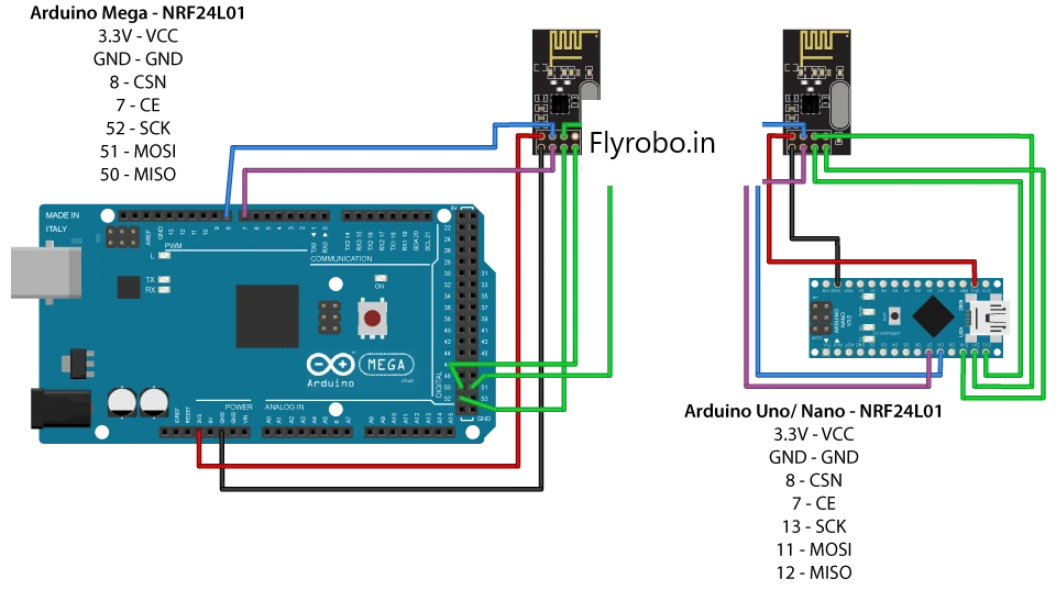
Circuit Diagram
Arduino Code
- Transmitter Code
#include#include #include RF24 radio(7, 8); const byte address[6] = "00001"; void setup() { radio.begin(); radio.openWritingPipe(address); radio.setPALevel(RF24_PA_MIN); radio.stopListening(); } void loop() { const char text[] = "Hello World"; radio.write(&text, sizeof(text)); delay(1000); }
- Receiver code
#INCLUDE#INCLUDE #INCLUDE RF24 RADIO(7, 8); // CE, CSN CONST BYTE ADDRESS[6] = "00001"; VOID SETUP() { SERIAL.BEGIN(9600); RADIO.BEGIN(); RADIO.OPENREADINGPIPE(0, ADDRESS); RADIO.SETPALEVEL(RF24_PA_MIN); RADIO.STARTLISTENING(); } VOID LOOP() { IF (RADIO.AVAILABLE()) { CHAR TEXT[32] = ""; RADIO.READ(&TEXT, SIZEOF(TEXT)); SERIAL.PRINTLN(TEXT); } }
I hope you learned something about the nRF module in this article and I hope you liked it. Thank you.


Leave a Comment