01 Feb

Hello,
In this tutorial, we are going to build a robotic car with speed sensors.
Hardware Required
Software Required
- Arduino IDE
- Robotic cars are one of the simplest Arduino projects and it has many benefits to it. It is an inexpensive robot and is the perfect choice for a first project if anyone want to get into the world of Arduino. A lot of you might be wondering what those black circular disks are which come with the chassis. Those are called as the "rotary encoders" and they, coupled with opto interrupter sensors, can be used to measure the speed and the distance measured. Not many people use these rotary encoders to measure speed.
- First let us understand how optical interrupter sensors work.
Optical Interrupter sensors
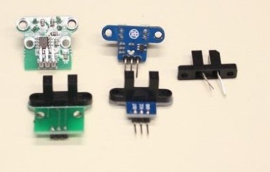
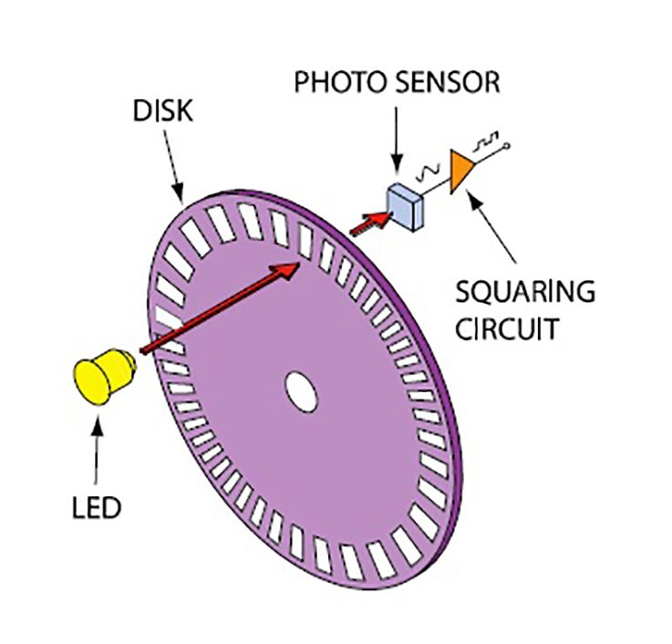
- Opto interrupters are an electronic component with many applications. In fact, one of the most common uses of this is in the mouse scroll. It consists of a light, usually an IR LED, and a phototransistor. There is a small gap between these two sensors. When the LED emits light onto the phototransistor, it completes the circuit and the current flows through it. So now when the opaque encodes moves in between the opto interrupter, it interrupts the flow of current.
- Rotary encoders have 20 equally spaces slots on them. So when the encoder rotates, it allows small pulses of light to reach the photo sensor. These pulses are further used to calculated the speed and the distance.
Calculating the speed
- To calculate the speed, we need the distance and the time required to cover it. We also need the circumference of the wheel.
- Generally the diameter of such rotary encoders is 66 mm. So the circumference is 207.4 mm.
-
-
- 66 x pi = 207.4 mm.
-
- So we can easily calculate the distance now from the number of revolutions of the encoder.
- Let us consider the case where the encoder has done 10 revolutions in a minute.
-
-
- Distance covered = 207.4 x 10 = 2074 mm = 2.074 meters
-
-
-
- Time taken to cover that distance = 60 seconds
-
-
-
- Speed = 2.074 / 60 = .034 m/s or 34 mm/s
-
- This is how the speed and the distance are calculated.
Circuit Diagram
- This Circuit diagram is pretty self explanatory.
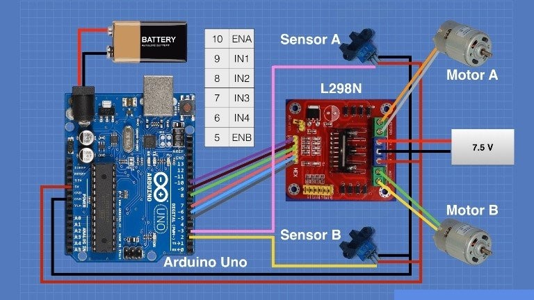
- The opto interrupt sensor signal pins are connected to the Arduino digital pins 2 and 3.
Arduino Code
const byte MOTOR_A = 3;
const byte MOTOR_B = 2;

const float stepcount = 20.00;


const float wheeldiameter = 66.10;


volatile int counter_A = 0;
volatile int counter_B = 0;


int enA = 10;
int in1 = 9;
int in2 = 8;


int enB = 5;
int in3 = 7;
int in4 = 6;


void ISR_countA()
{
  counter_A++;
}

void ISR_countB()
{
  counter_B++;
}


int CMtoSteps(float cm) {

  int result;
  float circumference = (wheeldiameter * 3.14) / 10;
  float cm_step = circumference / stepcount;

  float f_result = cm / cm_step;
  result = (int) f_result;

  return result;

}


void MoveForward(int steps, int mspeed)
{
   counter_A = 0;
   counter_B = 0;


   digitalWrite(in1, HIGH);
   digitalWrite(in2, LOW);

   digitalWrite(in3, HIGH);
   digitalWrite(in4, LOW);

   while (steps > counter_A && steps > counter_B) {

    if (steps > counter_A) {
    analogWrite(enA, mspeed);
    } else {
    analogWrite(enA, 0);
    }
    if (steps > counter_B) {
    analogWrite(enB, mspeed);
    } else {
    analogWrite(enB, 0);
    }
   }


  analogWrite(enA, 0);
  analogWrite(enB, 0);
  counter_A = 0;
  counter_B = 0;

}


void MoveReverse(int steps, int mspeed)
{
   counter_A = 0;
   counter_B = 0;


  digitalWrite(in1, LOW);
  digitalWrite(in2, HIGH);


  digitalWrite(in3, LOW);
  digitalWrite(in4, HIGH);


   while (steps > counter_A && steps > counter_B) {

    if (steps > counter_A) {
    analogWrite(enA, mspeed);
    } else {
    analogWrite(enA, 0);
    }
    if (steps > counter_B) {
    analogWrite(enB, mspeed);
    } else {
    analogWrite(enB, 0);
    }
    }


  analogWrite(enA, 0);
  analogWrite(enB, 0);
  counter_A = 0;
  counter_B = 0;

}


void SpinRight(int steps, int mspeed)
{
   counter_A = 0;
   counter_B = 0;

  digitalWrite(in1, LOW);
  digitalWrite(in2, HIGH);


  digitalWrite(in3, HIGH);
  digitalWrite(in4, LOW);


   while (steps > counter_A && steps > counter_B) {

    if (steps > counter_A) {
    analogWrite(enA, mspeed);
    } else {
    analogWrite(enA, 0);
    }
    if (steps > counter_B) {
    analogWrite(enB, mspeed);
    } else {
    analogWrite(enB, 0);
    }
   }


  analogWrite(enA, 0);
  analogWrite(enB, 0);
  counter_A = 0;
  counter_B = 0;

}


void SpinLeft(int steps, int mspeed)
{
   counter_A = 0;  //  reset counter A to zero
   counter_B = 0;  //  reset counter B to zero

  digitalWrite(in1, HIGH);
  digitalWrite(in2, LOW);

  digitalWrite(in3, LOW);
  digitalWrite(in4, HIGH);

   while (steps > counter_A && steps > counter_B) {

    if (steps > counter_A) {
    analogWrite(enA, mspeed);
    } else {
    analogWrite(enA, 0);
    }
    if (steps > counter_B) {
    analogWrite(enB, mspeed);
    } else {
    analogWrite(enB, 0);
    }
  }

  // Stop when done
  analogWrite(enA, 0);
  analogWrite(enB, 0);
  counter_A = 0;
  counter_B = 0;

}

void setup()
{
  // Attach the Interrupts to their ISR's
  attachInterrupt(digitalPinToInterrupt (MOTOR_A), ISR_countA, RISING);
  attachInterrupt(digitalPinToInterrupt (MOTOR_B), ISR_countB, RISING);

  // Test Motor Movement  - Experiment with your own sequences here

  MoveForward(CMtoSteps(50), 255);
  delay(1000);
  MoveReverse(10, 255);
  delay(1000);
  MoveForward(10, 150);
  delay(1000);
  MoveReverse(CMtoSteps(25.4), 200);
  delay(1000);
  SpinRight(20, 255);
  delay(1000);
  SpinLeft(60, 175);
  delay(1000);
  MoveForward(1, 255);


}


void loop()
{


}

Hot
-56 %
The Arduino Uno R3 Compatible board is an electronic hardware device used to build and program electronic circuits and projects. The board is based on..
₹574 ₹1,299

-34 %
L298N 2A Based Motor Driver is a high power motor driver perfect for driving DC Motors and Stepper Motors.
It uses the popular L298 motor driver IC..
₹108 ₹164

-51 %
This is an Optical slot speed measuring sensor for Arduino. Widely used in motor speed detection, pulse count, the position limit, etc.
The DO..
₹45 ₹92

-51 %
Details and Specifications:
This is 10pcs of each (total 30 pcs) jumper cable Dupont wire for Arduino.
High quality and in good working condit..
₹49 ₹99

-40 %
This is a DIY 4 wheel double-layer Robot car chassis kit. It includes the four pairs of Geared Motors and Wheels. The chassis used in this kit is tran..
₹599 ₹999

Leave a Comment