
Hello,
In this article, we will talk about the microcontroller board Arduino Pro Mini.
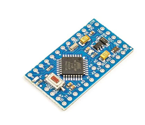
Arduino Pro mini is a small but quite powerful board. It is very similar to the Arduino Uno as they use the same processor. It is even more versatile than Uno as it has a small size and so it can be used in permanent embedded systems projects.
Arduino Pro Mini Pinout
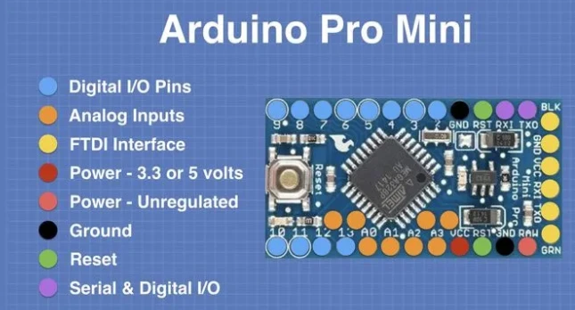
One of the advantages the Arduino pro mini has over the Uno is that it can have two additional analog input/output pins. This is mainly possible as the pro mini pins are surface mount whereas the Uno pins use female headers. The pro mini also has a both 5V and 3.3V pins. But for all these advantages, the Arduino Pro mini has a big disadvantage over the Uno. It does not contain any USB ports to connect it directly to a computer. Thus, it requires a device called as an FTDI adapter to connect it to a computer.
FTDI Adapter
FTDI is the short form of the semiconductor manufacturer Future technology devices International. In addition to FTDI adapters, this company also makes different sorts of video adapters. It has one mini USB port on one side and 6 male header pins on the other side.
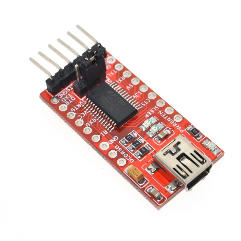
The FTDI adapter not only provides pins for data transfer, but it also provides pins for power supply to the Arduino board.
As Arduino mini has both 3.3V and 5V pins. And the FTDI adapter can supply both 3.3 and 5 volts but to select the voltage, we need to connect a jumper on the FTDI board. But you need to be careful about this. You cannot connect a 5V jumper and then connect the VCC pin to 3.3V. This can damage the Arduino board. So connect the jumpers properly.
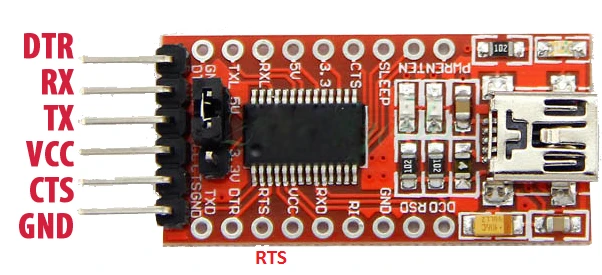
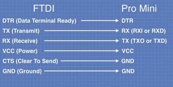
The connections from the FTDI to the pro mini board are listed as follows:
-
DTR- This pin is short for Data Terminal Ready. This pin sends a signal from the FTDI to the pro mini stating it is ready to send the data.
- TX- To transmit the data to the Arduino board.
- RX- To receiver the data from the Arduino board.
- VCC- Power supply pin. It can provide both 3.3 and 5 volts depending upon the jumper.
- GND- Ground pin.
- CTS- Clear to send pin. This means Arduino board will send the signal to FTDI adapter stating it is ready to receive the data.
Programming the Arduino board
Now that we have connected the Arduino board with the FTDI connector, it is time to program the Arduino board. To connect the FTDI adapter to the computer, you will need a mini USB cable. You will also need to install the required drivers for it to run properly. You can download and install the drivers from here.
After installing the drivers. Select the appropriate board from the boards menu. And then select the com port in which the FTDI adapter is connected.
Robotic Arm Control with Pro-Mini
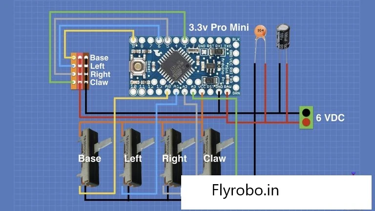
- This is a pretty simple demonstration as there are 4 potentiometers connected to 4 servos which make up for the robotic arm.
- The Signal pins of the 4 servos are connected to the digital pins 3, 5, 6 and 9.
Arduino Code
#includeServo base, left, right, claw ; int basePin = A0; int leftPin = A1; int rightPin = A2; int clawPin = A3; int baseValue = 0; int leftValue = 0; int rightValue = 0; int clawValue = 0; void setup() { base.attach(9); left.attach(6); right.attach(5); claw.attach(3); } void loop() { baseValue = map(analogRead(basePin), 0, 1023, 0, 180); leftValue = map(analogRead(leftPin), 0, 1023, 0, 180); rightValue = map(analogRead(rightPin), 0, 1023, 0, 180); clawValue = map(analogRead(clawPin), 0, 1023, 0, 180); base.write(baseValue); left.write(leftValue); right.write(rightValue); claw.write(clawValue); delay(400); }
Upload the code to the Arduino board via the FTDI adapter.
I hope you learned something about the Arduino pro mini board in this article and I hope you liked it. Thank you

Leave a Comment