
Hello,
In this tutorial-based article, we are going to learn about joysticks and their interfacing with Arduino.
Hardware Required
Software Required
-
Generally, when we hear the word Joystick, our minds go towards the gaming sector as joysticks are mostly used in that sector. Joysticks are highly used in gaming controllers.
-
They can also be used in the robotics industry to control and move robots.
- Everyone must have seen these kinds of joysticks on PlayStation controllers. All these joysticks work on the same principle.
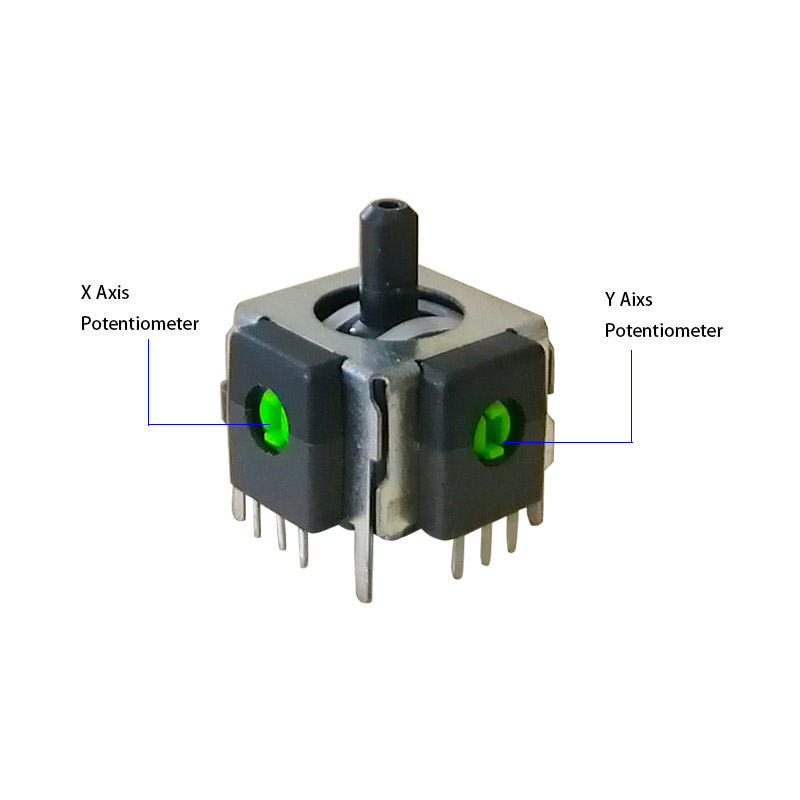
- These joystick controllers record only two-dimensional motion. So they contain two different potentiometers: one for the x-axis and another for the y-axis. These potentiometers are independent and of 10k.
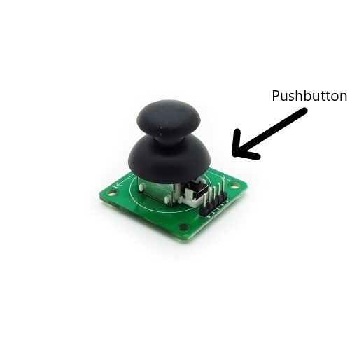
- Apart from this, the joystick also contains a pushbutton which can be used by pressing the joystick.
-
The basic principle behind a joystick is that every coordinate inside the joystick is assigned a function. So when the joystick is moved, the position is sent to the Arduino board. And it performs functions accordingly.
-
The position is first converted into resistance values by the potentiometer. These X and Y resistance values are sent to the Arduino board.
-
The functions are then performed accordingly.
-
The design for this motion is quite complicated. To move freely in two dimensions requires a complicated mechanism.
-
Here the gimbal mechanism is used. This mechanism allows free motion in two dimensions as it involves two axes.
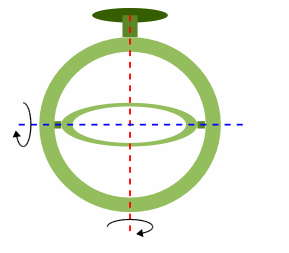
- Two shafts are used to indicate motion in two axes. The right-left motion is done using one shaft whereas the up and down motion is done using the second shaft.
- When the motion is on X-axis, only one shaft is pivoted. When the motion is on the y-axis, the other shaft is pivoted. But when the motion is diagonal, both the shafts are pivoted to provide motion in every direction.
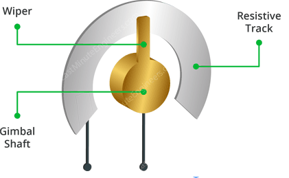
- A potentiometer is connected to each shaft. As the shaft rotates, the resistance of the potentiometer also changes. This resistance is then measured using the Arduino board.
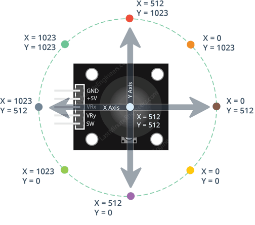
- The analog data is sent to the Arduino board via the ADC pin.
- The X and Y values can vary from 0 to 1023 as they go from one extreme to another.
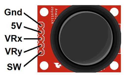
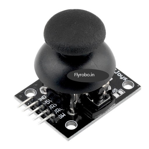
- The GND is the ground pin.
- The VCC is the power supply pin. It is connected to the 5V pin on Arduino.
- The VRx pin is the pin that gives the X-axis data as the output. It shows how far right or left is the joystick pushed.
- The very pin is the pin that gives the Y-axis data as the output. It shows how far up or down has the Joystick been pushed.
- The SW pin is the output pin for the push button. It gives out digital output for when the pushbutton has been pressed. The output for when the button is pressed will be LOW.
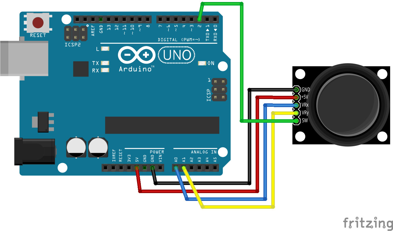
Interfacing with Arduino
|
Pins on Joystick |
Pins on Arduino Uno |
|
GND |
GND |
|
5V |
5V |
|
VRx |
A0 |
|
VRy |
A1 |
|
SW |
Digital pin 2 |
Arduino Code
const int SW_pin = 2;
const int X_pin = 0;
const int Y_pin = 1;

void setup()
{
  pinMode(SW_pin, INPUT);
  digitalWrite(SW_pin, HIGH);
  Serial.begin(9600);
}

void loop()
{
  Serial.print("Switch: ");
  Serial.print(digitalRead(SW_pin));
  Serial.print(" | ");
  Serial.print("X-axis: ");
  Serial.print(analogRead(X_pin));
  Serial.print(" | ");
  Serial.print("Y-axis: ");
  Serial.print(analogRead(Y_pin));
  Serial.println(" | ");
  delay(200);
}
- Upload the code to the Arduino board.
- This code will show the data of X output, Y output, and the whether the pushbutton is pressed or not on the Serial Monitor.


Leave a Comment